DK424 Configuration
Features Capacities
Strata DK I&M 6/00
4-7
DK424 Configur
at
ion
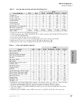
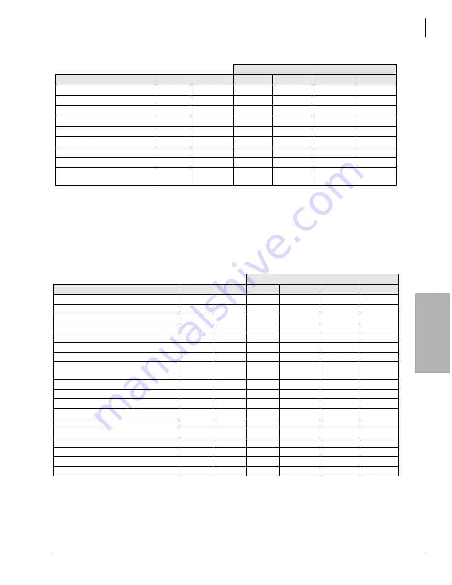
Table 4-7
Line Capacities and Universal Printed Circuit Board Slots
DK424
Lines and PCB Slots
DK14
DK40i
RCTUA
RCTUBA/BB
RCTUC/D
RCTUE/F
Universal slots
0
4
1
6
12
36
54
CO lines – loop start
4
12
2
16
2
48
2
144
2
200
2
CO lines – ground start
0
12
16
2
40
2
136
2
200
2
DID lines (analog)
0
12
16
3
40
3
136
3
200
3
Tie lines (analog)
0
12
16
3
40
3
136
3
200
3
T1 (DS-1) lines each)
0
0
0
48
4
144
4
192
4
ISDN BRI (S/T or U) B channel lines
0
12
8
5
16
5
16
5
16
5
ISDN PRI (T) B channel lines
0
0
0
47
6
141
6
188
6
Squared System Maximum
(lines + stations)
4 lines +
4 stations
12 lines +
12 stations
16 lines +
16 stations
48 lines +
48 stations
144 lines +
144 stations
200 lines +
200 stations
1. There are four universal slots in the DK40i expansion unit.
2. All CO line capacities assume a PIOU, PIOUS, PEPU, RSSU, or RSIU is installed for RCTUBA/BB, RCTUC/D or RCTUE/
F, but no Caller ID RCIU2/RCIS PCBs.
3. Limits apply to analog DID and Tie lines, not T1 DID/Tie lines.
4. T1 lines can be loop start, ground start, Tie, or DID (maximum 24 lines per unit, any type or combination).
5. BRI lines provide CO line services, including Caller ID, DID and Direct Inward Lines (DIL).
6. PRI lines provide CO line services, including Caller ID, ANI, DID, Tie, POTS, FX and DIL.
Table 4-8
Station and Peripherals Capacities
DK424
Stations
DK14
DK40i
RCTUA
RCTUBA/BB
RCTUC/D
RCTUE/F
Add-on modules (DADM)
8
12
12
40
120
200
Attendant consoles
0
0
0
2
4
4
DKT 2004-CT Cordless Telephones
8
28
32
80
240
336
DKT 2004-CT simultaneous calls
8
9
9
9
9
9
Door locks
2
3
4
5
5
5
Door phones (MDFB)
6
9
9
12
12
12
DSS consoles
0
3
3
4
8
8
ISDN BRI station circuits TE-1 and TA
(2B+D per circuit)
1
1. ISDN BRI TE-1 and TA include ISDN telephones, modems, video conference interfaces, etc. Up to two stations (TE-1 and/or
TA) can connect to and share one BRI S-type circuit. Only one station can connect to a BRI U-type circuit.
0
10
8
16
40
64
Handset OCA stations
8
28
32
80
240
336
Off-premise stations
2
20
32
80
232
328
PDIU-DS
2
2. Speaker OCA, PDIU and RPCI capacity is determined by 2B channel slot availability and power supply limits.
7
24
31
79
160
208
RPCI-DI used for data + TAPI, per system
8
24
32
80
144
200
RPCI-DI used for TAPI only: per cabinet
2
N/A
N/A
32
40
40
40
RPCI-DI used for TAPI only: per system
2
8
24
32
80
186
280
Speaker OCA stations
8
28
32
80
160
208
Standard stations
2
20
24
72
232
328
Telephones – DKT
8
28
3
3. To install the maximum of 28 total DKTs and EKTs in the DK40i, up to 16 of the stations can be EKTs and at least 8 of the
stations must be DKTs.
32
4
4. Maximum capacity of DKT/EKT stations per DK424 cabinet is 62, less for EKT 2000, 3000 (Power Factor limitation).
80
4
240
4
336
4
Telephones – EKT
0
16
3
32
4
80
4
240
4
328
4
Summary of Contents for Strata AirLink DK40i
Page 22: ...Introduction Related Documents Media xx Strata DK I M 6 00 ...
Page 48: ...DK14 Installation DK14 Wiring Diagrams 1 26 Strata DK I M 6 00 ...
Page 220: ...DK424 Installation Remote Cabinet Installation Instructions 5 68 Strata DK I M 6 00 ...
Page 262: ...DK424i Configuration Primary Reserve Power Cabinet Hardware 6 42 Strata DK I M 6 00 ...
Page 450: ...Universal Slot PCB Wiring Option Interface PCB Wiring Diagrams 10 42 Strata DK I M 6 00 ...
Page 592: ...Peripheral Installation Enhanced 911 Service E911 12 84 Strata DK I M 6 00 ...
Page 616: ...ACD Installation Spectrum Electronic Wall Boards 13 24 Strata DK I M 6 00 ...
Page 634: ...Fault Finding Fault Isolation Flowcharts 14 18 Strata DK I M 6 00 ...
Page 704: ...ISDN Interfaces ISDN Disconnect Cause Code 16 54 Strata DK I M 6 00 ...


