– 2 –
CONTENTS
1. SPECIFICATIONS .......................................................................................................................... 3
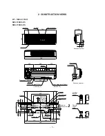
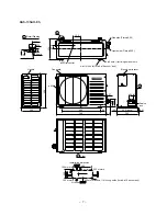
2. CONSTRUCTION VIEWS .............................................................................................................. 5
2-1.
Indoor Unit ........................................................................................................................................ 5
2-2.
Outdoor Unit ..................................................................................................................................... 6
3. WIRING DIAGRAM ........................................................................................................................ 8
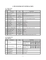
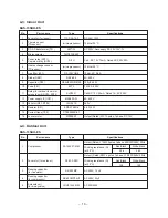
4. SPECIFICATIONS OF ELECTRICAL PARTS ............................................................................... 9
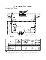
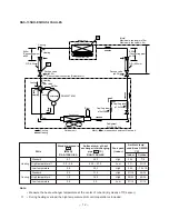
5. REFRIGERANT CYCLE DIAGRAM ............................................................................................. 11
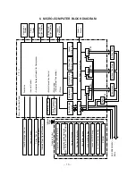
6. MICRO-COMPUTER BLOCK DIAGRAM .................................................................................... 13
7. OPERATION DESCRIPTIONS ..................................................................................................... 14
7-1.
FAN ONLY Operation ...................................................................................................................... 14
7-2.
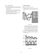
COOL Operation ............................................................................................................................. 14
7-3.
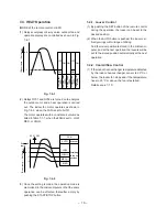
DRY Operation ................................................................................................................................ 15
7-4.
HEAT Operation .............................................................................................................................. 16
7-5.
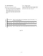
AUTO Operation ............................................................................................................................. 17
7-6.
ECONO. Mode ................................................................................................................................. 18
7-7.
Current Limit Control ..................................................................................................................... 18
7-8.
High-Temperature Limit Control (Heating Operation) ................................................................. 19
7-9.
Low-Temperature Limit Control (Cooling Operation) .................................................................. 19
7-10. Cool Airflow Prevention Control (Heating Operation) ................................................................. 19
7-11. Defrost Operation ........................................................................................................................... 20
7-12. Auto Restart Function .................................................................................................................... 21
8. INSTALLATION PROCEDURE .................................................................................................... 23
8-1.
Safety Cautions .............................................................................................................................. 23
8-2.
Installation Diagram of Indoor and Outdoor Units ...................................................................... 25
8-3.
Installation ...................................................................................................................................... 26
8-4.
Indoor Unit ...................................................................................................................................... 28
8-5.
Outdoor Unit ................................................................................................................................... 34
8-6.
Others .............................................................................................................................................. 37
9. TROUBLESHOOTING CHART .................................................................................................... 38
9-1.
What to be Prechecked First ......................................................................................................... 38
9-2.
Primary Judgement of Trouble Sources ....................................................................................... 40
9-3.
Troubleshooting Flowcharts .......................................................................................................... 44
9-4.
How to Check the Remote Control (Including the Indoor P.C. Board) ........................................ 50
10. PART REPLACEMENT ................................................................................................................ 55
10-1. Indoor Unit ...................................................................................................................................... 55
10-2. Microcomputer ............................................................................................................................... 57
10-3. Outdoor Unit ................................................................................................................................... 58
11. CAUTIONS ON REPLACEMENT OF P.C. BOARD ASSEMBLY ................................................ 59
12. EXPLODED VIEWS AND PARTS LIST ....................................................................................... 61
12-1. Indoor Unit (1) ................................................................................................................................. 61
Indoor Unit (2) ................................................................................................................................. 63
Indoor Unit (3) ................................................................................................................................. 65
12-2. Outdoor Unit ................................................................................................................................... 66
• This air conditioner is charged with HFC (R-410A)
that doesn't deplete the Ozone layer.
• This air conditioner requires special service tools
for the refrigerant R-410A.
Summary of Contents for SRAS-13SKH-ES
Page 53: ... 53 9 4 2 P C Board Layout Bottom View Top View ...
Page 68: ......

