


2 Troubleshooting Procedures
Satellite P300 and Satellite Pro P300 Maintenance Manual (960-Q08)
1
2
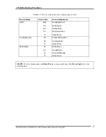
2.1 Troubleshooting
Chapter 2 describes how to determine which Field Replaceable Unit (FRU) in the computer
is causing the computer to malfunction.
The FRUs covered are:
1. Power supply
6. Touch pad
11. Wireless LAN
2. System Board
7. Display
12. Sound
3. USB FDD
8. Optical Disk Drive
13, Finger Print Board
4. 2.5” HDD
9. Modem
14, B
lue
tooth
5. Keyboard
10. LAN
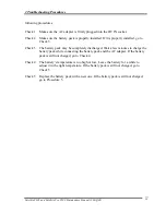
The Test Program operations are described in Chapter 3. Detailed replacement procedures are
described in Chapter 4.
NOTE: After replacing the system board or CPU, it is necessary to execute the subtest 01
initial configuration of the 3.3 Setting of the hardware configuration in Chapter
3. Also update with the latest BIOS as described in Appendix G “BIOS Rewrite
Procedures”
After replacing the LCD, update with the latest EC/KBC as described in
Appendix H “EC/KBC Rewrite Procedures” to set the SVP parameter.
The implement for the Diagnostics procedures is referred to Chapter 3. Also, following
implements are necessary:
1.
Phillips screwdrivers (For replacement procedures)
2.
Implements for debugging port check
•
•
•
•
Toshiba MS-DOS system FD
RS-232C cross cable
Test board with debug port test cable
PC for displaying debug port test result
Summary of Contents for Satellite P300
Page 12: ...Satellite P300 Maintenance Manual 960 Q08 12 ...
Page 43: ... CONFIDENTIAL 2 1 Chapter 2 Troubleshooting Procedures ...
Page 99: ...Troubleshooting Procedures Satellite P300 and Satellite Pro P300 Maintenance Manual 54 ...
Page 311: ...Appendix F Wiring Diagrams F 2 LAN Loopback Connector Magnia 3100 Maintenance Manual F 2 ...
Page 315: ...Reliability Satellite P300 and Satellite Pro P300 Maintenance Manual 960 Q08 I 2 ...


