background image

RBC-MTSC2 Mini Touch Screen Controller 

Installation & Owner Manual 

14

6.4.7.  Appearance 

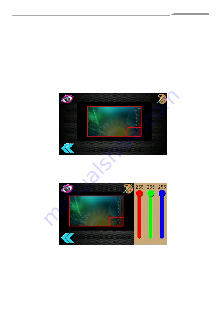
The background image and logo can be altered on this screen. The images must have been 
downloaded to the controller using the Pyrus R/C configuration software. 

Tap the background rectangle to show the currently installed images. Tap the required image to 
select. The background image can be disabled using the slider switch in the top left corner of the 
screen. If disabled, a plain white background will be used, which can be tinted using the colour 
adjustment sliders (see below). 

Tap the logo rectangle to show the currently installed logos. Tap the required logo to select. The 
logo can be disabled using the slider switch in the top left corner of the screen. 

Colour tones of the background image can be adjusted to change appearance. Touch the palette 
icon to show and hide the RGB colour sliders. 

Summary of Contents for RBC-MTSC2

Page 1: ...RBC MTSC2 Installation Manual Mini Touch Screen Controller With 7 day Scheduler RBC MTSC2 v1 00 2020 ...

Page 2: ...onfiguration Menu Icons 11 6 4 3 General R C Setup 12 6 4 4 Frost Protection 12 6 4 5 User Interface Setup 13 6 4 6 DN Code Editing 13 6 4 7 Appearance 14 6 4 8 Clock and Scheduler 15 6 4 9 Date and Time 15 6 4 10 Scheduler 15 6 4 11 Programming Control Events 16 6 4 12 Adding or Editing Control Events 16 6 4 13 Deleting Control Events 16 6 4 14 Copying Event List 17 6 4 15 Diagnostics 18 6 4 16 M...

Page 3: ...ervicing WARNING Moving parts Do not operate unit with grille removed Stop the unit before the servicing CAUTION High temperature parts You might get burned when removing this panel CAUTION High temperature parts You might get burned when removing this panel CAUTION Do not touch the aluminium fins of the unit Doing so may result in injury CAUTION Do not touch the aluminium fins of the unit Doing s...

Page 4: ...REQUIREMENT For power supply wiring strictly conform to the Local Regulation in each country For wiring of power supply of the outdoor units follow the Installation Manual of each outdoor unit Perform the electric wiring so that it does not come to contact with the high temperature part of the pipe The coating may melt resulting in an accident After connecting wires to the terminal blocks provide ...

Page 5: ...nments Set DN codes Set central addresses Leak detection warning symbols to complement the current Toshiba solution Text inputs for instructions example Error contact reception tel 1234 Use CN61 connection to set back for energy saving for un occupied space Real time clock and 7 day scheduler MAIN FUNCTIONS FUNCTION COMMAND INPUT STATUS OUTPUT ON OFF Status Operation Mode Auto Heat Cool Dry Fan On...

Page 6: ...een Controller is powered on connection to the indoor unit A B terminals 4 2 USB The USB interface micro USB A B socket located on the bottom of the enclosure is used for configuration via a PC and for upgrading the firmware Ensure that the correct USB driver has been installed prior to connecting the Mini Touch Screen Controller to a PC 4 3 Firmware Updates IMPORTANT NOTICE Please check our websi...

Page 7: ...RBC MTSC2 Mini Touch Screen Controller Installation Owner Manual 7 5 Dimensions 5 1 Fixing Frame 15 mm 74 mm 141 mm Fixing holes Cable entry ...

Page 8: ...ual 8 6 User Interface 6 1 Start Up Initialising start up display screen Remote Controller communication initialisation screen can take up to 5 minutes to complete when system is auto addressing 6 2 Ready After initialisation the controller is ready to switch on ...

Page 9: ...ault View Pressing the power icon displays the default screen 6 3 1 Error and Filter Sign Indicator The indicator is displayed whenever an error is detected or a filter needs cleaning 6 3 2 Error Code Tap the error code to display the error description and service information ...

Page 10: ...oller Installation Owner Manual 10 6 4 Control Panel Tap the handle on the left of the screen to open the control panel The control panel shows the current time and date It also gives access to the clock scheduler configuration screen ...

Page 11: ...om left hand corner of the screen Now keeping your finger on the left hand corner of the screen do not remove release your right hand finger and tap the bottom right hand corner of the screen four times with your finger Executing this sequence correctly will reveal the configuration menu above 6 4 2 Configuration Menu Icons 1 General R C setup 2 User interface setup 3 DN code editing 4 Appearance ...

Page 12: ...ensor in the controller is selected for the return air reading due to the possibility of invalid readings from the indoor unit sensor while the fan is not running Once enabled the return air temperature will be constantly monitored and the following strategy is executed Frost Protection State Return Air Temperature Action Inactive 8 0 C 1 Save current indoor unit state 2 Set indoor unit as follows...

Page 13: ... 6 4 6 DN Code Editing To change DN code settings use up down arrow to move between DN codes To change data settings use up down arrow to change value then press the green Send button To exit DN code use blue Back button To change to a different indoor unit tap the air conditioner icon The selection window will be displayed Available units will be highlighted Tap the required unit to edit its DN c...

Page 14: ... select The background image can be disabled using the slider switch in the top left corner of the screen If disabled a plain white background will be used which can be tinted using the colour adjustment sliders see below Tap the logo rectangle to show the currently installed logos Tap the required logo to select The logo can be disabled using the slider switch in the top left corner of the screen...

Page 15: ...ll reset to 00 00 01 01 2016 Tap the date or time to display the appropriate setting window Date setting Time setting Tap the item to adjust and use the up down arrows to change Press and hold an arrow to speed up the adjustment 6 4 10 Scheduler The 7 day scheduler allows up to 8 control events to be programmed each day Enable or disable the scheduler by tapping the toggle switch Each timeline sum...

Page 16: ...ng an existing event or the Add Event button will bring up the event edit window Tap the time or control icons to adjust event settings Selecting the for any control setting will prevent that setting from being actioned by the scheduler 6 4 13 Deleting Control Events Tap the Delete Event toggle button to show hide the delete button next to each event Tapping the delete button removes the correspon...

Page 17: ...l bring up the Copy Event List window The events for the currently selected day can be copied to any of the other days of the week Tapping on a day will show hide the selection indicator In the example above Monday is the source and Tuesday Wednesday Thursday and Friday have been selected to receive a copy of Mondays event list ...

Page 18: ...nit The thermometer icon indicates which is selected as the controlling return air sensor 2 The number of units in error 3 The number of units with the filter sign active 4 The occupancy state if occupancy strategy is enabled MTSC1 only The filter reset button is displayed if the filter sign count is non zero Tapping the air conditioner icon will display the status of all connected indoor units ...

Page 19: ...Will be displayed when certain configuration changes require the indoor units and Remote Controller to be restarted 6 4 18 Back Button Tap to exit and return to previous screen Tap to exit and return to previous screen When changing configuration settings modified settings will be saved and the Remote Controller redisplays the HVAC control screen ...

Page 20: ...o be demonstrated without being connected to an indoor unit This screen is displayed if the controller is only connected via USB At this point use the PC configuration software to setup the controller download new images or tap the button to enter demonstration mode 6 4 20 Demonstration Mode The controller pretends to be connected to 2 indoor units one with an active error the other with an active...

Page 21: ...RBC MTSC2 Mini Touch Screen Controller Installation Owner Manual 21 6 5 Version History and New Features Guide 6 5 1 Version Information v1 00 initial release ...

Page 22: ...ion error between indoor header and follower units E19 Outdoor header units quantity error E20 Other line connected during automatic address E23 Sending error in communication between outdoor units E25 Duplicated follower outdoor address E26 Decrease of No of connected outdoor units E28 Follower outdoor unit error E31 IPDU communication error F01 Indoor TCJ sensor error F02 Indoor TC2 sensor error...

Page 23: ...ses L28 Maximum number of outdoor units exceeded L29 No of IPDU error L30 Auxiliary interlock in indoor unit L31 IC error P01 Indoor fan motor error P03 Discharge temp TD1 error P04 High pressure switch detection error P05 Phase missing detection Phase order error P07 Heat sink overheat error P10 Indoor overflow error P12 Indoor fan motor error P13 Outdoor liquid back detection error P15 Gas leak ...

Page 24: ...port toshiba ac com Plymouth Toshiba Carrier UK Limited Porsham Close Belliver Industrial Estate Plymouth Devon PL6 7DB Tel 0870 843 0333 sales support toshiba ac com Departmental Contact Details Sales 0845 850 8924 sales support toshiba ac com Projects 01372 220 266 projects uk toshiba ac com Spares 0870 843 0333 opt 3 spares toshiba ac com Warranty 0870 843 0333 opt 6 warranty toshiba ac com Tra...

Reviews: