EN
17
Super Digital Inverter
7
ELECTRICAL WORK
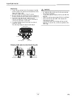
1. Remove valve cover screw.
2. Pull the valve cover downward to remove it.
Wiring between Indoor Unit and Out-
door Unit
The dashed lines show on-site wiring.
•
Connect the indoor/outdoor connecting wires to the
identical terminal numbers on the terminal block of each
unit.
Incorrect connection may cause a failure.
For the air conditioner, connect a power wire with the
following specifications.
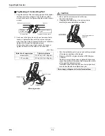
CAUTION
•
Wrong wiring may cause a burn-out of some electrical
parts.
•
Be sure to use the cord clamps attached to the product.
•
Do not damage or scratch the conductive core or inner
insulator of the power and inter-connecting wires when
peeling them.
•
Use the power and Inter-connecting wires with specified
thicknesses, specified types and protective devices
required.
Valve cover
Piping cover
Indoor/outdoor
connecting wires
Power wire
Model RAV-
SP40, SP45, SP56
Power supply
220-240 V~, 50 Hz
Maximum running current
15 A
Installation fuse rating
16 A (all types can be used)
Power wire
H07 RN-F or 60245 IEC 66
(2.5 mm
2
or more)
Indoor/outdoor connecting
wires
H07 RN-F or 60245 IEC 66
(1.5 mm
2
or more)
L
N
1
2
3
1
2
3
(Main circuit)
(Indoor/outdoor
connecting wires)
Outdoor unit
Remote
controller
Indoor unit
Earth
Leakage
breaker
Input power
220-240 V~,
50 Hz

