– 83 –
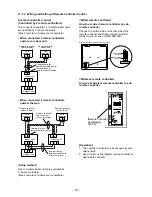
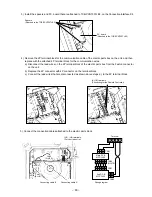
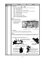
3) Install the spacers and P.C. board that are attached to TCB-PCNT30TLE2, on the Connection Interface Kit.
Spacers
(Attached to the TCB-PCNT30TLE2)
P.C. board
(Attached to the TCB-PCNT30TLE2)
(A), (B) terminals
(Connecting for the Remote Controller)
CN41
(BLUE)
CN41
(BLUE)
A
(U3), (U4) terminals
(For central control)
CN50
(WHITE)
CN41
(BLUE)
CN51
Connecting cable B
Connecting cable A
Wiring diagram
3
3
3
4 5
1
1
2
1
3 4 5
2
1
3 4 5
2
1
3 4 5
2
1
B
U
3
U
4
Terminal
Main P.C. B
MCC-1402
CN41
CN50
(WHITE)
CN51
CN40
Sub P.C. B
MCC-1440
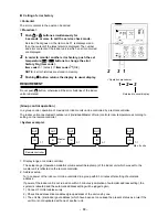
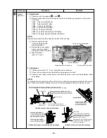
4) Remove the 2P terminal block for the communication cable of the electric parts box on the unit, and then
replace with the attached 4P terminal block for the communication wires.
a) Disconnect the lead wires on the 2P terminal block of the electric parts box from the Faston connector
on the unit.
b) Replace the 2P connector with 4P connector on the terminal block.
c) Connect the lead wires that are disconnected as shown above steps a), to the 4P terminal block.
5) Connect the connection cables attached to the electric parts block.


