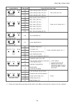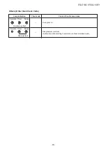
Error mode detected by outdoor unit
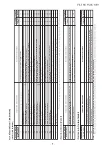
Operation of diagnostic function
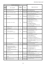
Check
code
Indoor
unit
F04
F06
F07
F12
F15
F08
F13
F31
L10
L29
P07
P15
P19
H01
H02
Cause of operation
Disconnection, short of discharge temp. sensor
(TD)
Disconnection, short of outdoor temp. sensor
(TE)
Disconnection, short of outdoor temp. sensor
(TL)
Disconnection, short of suction temp. sensor
(TS)
Miss-mounting of outdoor temp. sensor (TE, TS)
Disconnection, short of outside temp. sensor
(TO)
Disconnection, short of heat sink temp. sensor
(TH)
Outdoor P.C. EEPROM error
Unset jumper of service P.C. board
Communication error between outdoor P.C.
board MCU
Heat sink overheat error
∗
Heat sink temp. sensor detected over specified
temperature.
Detection of gas leak
∗
Discharge temp. sensor (TD), Suction temp.
sensor (TS) detected temperature over
specified temp.
4-way valve inverse error
∗
After heating operation has started, indoor
heat exchanger temp. lowers under the
specified temp.
∗
After heating operation has started, outdoor
heat exchanger / suction temp. rises over the
specified temp.
Compressor break down
∗
Although operation has started, operation
frequency decreases and operation stops.
Compressor lock
∗
Over-current detection after compressor
start-up
Status of
air conditioner
Stop
Stop
Stop
Stop
Stop
Continue
Stop
Stop
Stop
Stop
Stop
Stop
Stop
Stop
Stop
Condition
Displayed when
error is detected
Displayed when
error is detected
Displayed when
error is detected
Displayed when
error is detected
Displayed when
error is detected
Displayed when
error is detected
Displayed when
error is detected
Displayed when
error is detected
Displayed when
error is detected
Displayed when
error is detected
Displayed when
error is detected
Displayed when
error is detected
Displayed when
error is detected
Displayed when
error is detected
Displayed when
error is detected
Judgment and measures
1. Check discharge temp. sensor (TD).
2. Check outdoor P.C. board.
1. Check temp. sensor (TE).
2. Check outdoor P.C. board.
1. Check temp. sensor (TL).
2. Check outdoor P.C. board.
1. Check suction temp. sensor (TS).
2. Check outdoor P.C. board.
1. Check temp. sensor (TE, TS).
2. Check outdoor P.C. board.
1. Check outside temp. sensor (TO).
2. Check outdoor P.C. board.
1. Check outdoor P.C. board.
(Q201 is incorporated in TH sensor.)
1. Check outdoor P.C. board.
1. Outdoor service P.C. board
Check model type setting jumper wire.
1. Check outdoor P.C. board
2. Connection check for each P.C. board.
1. Check screw tightening between PC. Board and heat
sink and check radiator grease.
2. Check heat sink blast path.
1. Check gas leak, recharge
2. Check full open of service valve.
3. Check PMV (Pulse Motor Valve).
4. Check broken pipe.
5. Check discharge temp. sensor (TD), suction temp.
sensor (TS).
1. Check operation of 4-way valve.
2. Check outdoor heat exchanger (TE), suction temp.
sensor (TS).
3. Check indoor heat exchanger sensor (TC).
4. Check 4-way valve coil.
5. Check PMV (Pulse Motor Valve).
1. Check power supply voltage.
2. Overload operation of refrigerating cycle
1. Trouble of compressor (Lock, etc.): Replace compressor.
2. Wiring error of compressor (Open phase)
FILE NO. SVM-18039
- 43 -
Summary of Contents for RAV-RM1101BTP Series
Page 18: ...RM56 type RM80 type RM110 RM140 type FILE NO SVM 18039 18 ...
Page 19: ...3 WIRING DIAGRAM FILE NO SVM 18039 19 ...
Page 34: ...5 3 Indoor Print Circuit Board MCC 1631 FILE NO SVM 18039 34 ...
Page 89: ...11 EXPLODED VIEWS AND PARTS LIST 11 1 RAV RM561BTP E RAV RM561BTP TR FILE NO SVM 18039 89 ...
Page 91: ...11 2 RAV RM801BTP E RAV RM801BTP TR FILE NO SVM 18039 91 ...
Page 94: ...11 6 RAV RM1101BTP E RAV RM1101BTP TR RAV RM1401BTP E RAV RM1401BTP TR FILE NO SVM 18039 94 ...

