


1 2
END
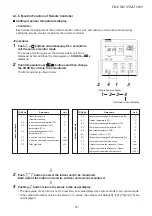
Operation
<Operation procedure>
2
1
SET
TIME
TIMER SET
TEST
FILTER
LL
RESET
TEMP.
CL
FAN
SAVE
A
A
SWING/FIX
VENT
MODE
ON / OFF
UNIT LOUVER
T
1 2 3
END
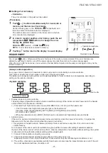
<Operation procedure>
3
1
2
SET
TIME
TIMER SET
TEST
FILTER
LL
RESET
TEMP.
P
P
CL
FAN
SAVE
A
A
SWING/FIX
VENT
MODE
ON / OFF
UNIT LOUVER
T
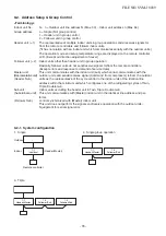
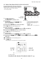
9-4. Confirmation of Indoor Unit No. Position
1. To know the indoor unit addresses though position of the indoor unit body is recognized
• In case of individual operation (Wired remote controller : indoor unit = 1 : 1)
(Follow to the procedure during operation)
<Procedure>
1
Push
ON / OFF
button if the unit stops.
2
Push
UNIT LOUVER
button.
Unit No.
1-1
1-1
1-1
1-1
1-1
is displayed on LCD.
(It disappears after several seconds.)
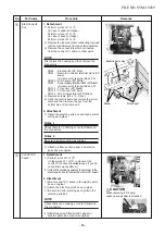
The displayed unit No. indicate line address and indoor
unit address. (When other indoor units are connected to
the identical remote controller (Group control unit), other
unit numbers are also displayed every pushing
UNIT LOUVER
button.
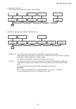
2. To know the position of indoor unit body by address
• To confirm the unit No. in the group control
(Follow to the procedure during operation) (in this procedure, the indoor units in group control stop.)
<Procedure>
The indoor unit numbers in the group control are
successively displayed, and fan, louver, and drain
pump of the corresponding indoor unit are turned on.
(Follow to the procedure during operation)
1
Push
VENT
and
TEST
buttons simultaneously
for 4 seconds or more.
• Unit No.
is displayed.
• Fans and louvers of all the indoor units in the
group control operate.
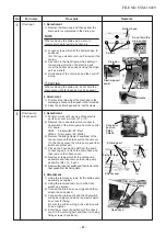
2
Every pushing
UNIT LOUVER
button, the unit
numbers in the group control are
successively displayed.
• The unit No. displayed at the first time indicates
the header unit address.
• Fan and louver of the selected indoor unit only
operate.
3
Push
TEST
button to finish the procedure.
All the indoor units in the group control stop.
FILE NO. SVM-18039
- 82 -
Summary of Contents for RAV-RM1101BTP Series
Page 18: ...RM56 type RM80 type RM110 RM140 type FILE NO SVM 18039 18 ...
Page 19: ...3 WIRING DIAGRAM FILE NO SVM 18039 19 ...
Page 34: ...5 3 Indoor Print Circuit Board MCC 1631 FILE NO SVM 18039 34 ...
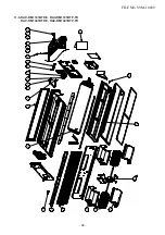
Page 89: ...11 EXPLODED VIEWS AND PARTS LIST 11 1 RAV RM561BTP E RAV RM561BTP TR FILE NO SVM 18039 89 ...
Page 91: ...11 2 RAV RM801BTP E RAV RM801BTP TR FILE NO SVM 18039 91 ...
Page 94: ...11 6 RAV RM1101BTP E RAV RM1101BTP TR RAV RM1401BTP E RAV RM1401BTP TR FILE NO SVM 18039 94 ...