


–
16
–
Item
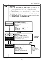
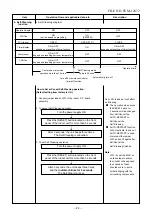
2. Indoor fan
motor control
Operation flow and applicable data, etc.
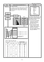
<In cooling operation>
(This operation controls the fan speed at indoor unit side.)
The indoor fan (cross flow fan) is operated by the phase-
control induction motor. The fan rotates in 5 stages in
MANUAL mode, and in 5 stages in AUTO mode, respec-
tively. (Table 1)
Description
* Symbols
UH
: Ultra High
H
: High
M+
:
M
: Medium
L+
: Low+
L
: Low
L-
: Low–
UL
: Ultra Low
SUL
: Super Ultra Low
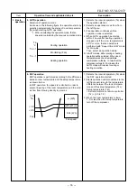
(Fig. 1)
(Fig. 2)
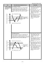
+2.5
Ta
[˚C]
+2.0
+1.5
+1.0
+0.5
Tsc
a
b
c
d
e
M+(WB)
*3
*4
*5
L(W6)
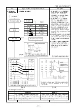
Air volume AUTO
L
L+
M
M+
H
W6
(L + M) / 2
W9
(M + H) / 2
WC
Indication
Fan speed
Fan speed setup
COOL ON
AUTO
MANUAL
*3 : Fan speed = (M + –L) x 3/4 + L
*4 : Fan speed = (M + –L) x 2/4 + L
*5 : Fan speed = (M + –L) x 1/4 + L
(Linear approximation
from M+ and L)
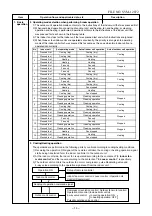
(Table 1) Indoor fan air flow rate
* The values of fan speed and air flow
volume indicate on the table are measured
when the louver is inclined downward.
Fan speed and air flow volume broadly
vary with position of louver.
1) When setting the fan speed to L,
L+, M, M+ or H on the remote
controller, the operation is
performed with the constant
speed shown in Fig. 1.
2) When setting the fan speed to
AUTO on the remote controller,
revolution of the
controlled to the fan speed lev
shown in Fig. 2 and T
according to the setup temper
ture, room temper
exchanger temperature.
ature, and heat
a-
able 1
el
fan motor is
Fan speed
Air flow rate
(rpm)
(m3/h)
WF
UH
1240
630
WE
H
1170
582
WD
UH
M+
UH
1140
563
WC
H
H
1100
536
WB
M+
M+
M+
1000
469
WA
M
1000
469
W9
M
L+
960
443
W8
L
870
383
W7
L+
L-
L+
850
369
W6
L
L
760
309
W5
L-
UL
L-
760
309
W4
UL
UL
700
269
W3
SUL
SUL
650
236
W2
SUL
500
135
W1
500
135
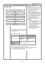
RAS-M07N3KV2-E
Fan speed
level
COOL
HEAT
DRY
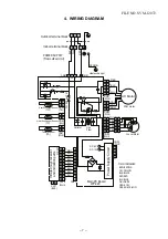
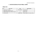
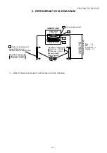
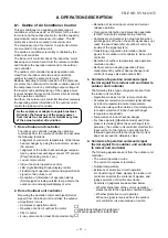
FILE NO. SVM-12072


