background image

Toshiba XXXXXXX(<SanSerif1>X/X)

3

Outdoor Unit

Installation Manual

3

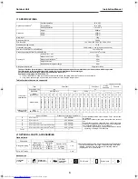
SPECIFICATIONS

The specifications for performance of this air conditioner differs depending on the combination of the indoor units which are operated.
The information in this specifications table applies for the combinations with the catalogue.
For operation, read the owner's manual packed with the indoor unit.
Equipment complying with IEC 61000-3-12.

*1 If the air conditioner is used in conditions other than the above, the safety protection functions may be activated.
*2 If any 4-way cassette type is connected, the maximum for total unit pipe length is 40m.

Table of models that can be connected

4

OPTIONAL PARTS, ACCESSORIES

Optional parts

Accessories

Operating conditions 

*1

Cooling operation

10 to 43°C

Dry operation

10 to 43°C

Heating operation

–10 to 22°C

Dimension

Height

890mm

Width

900mm

Depth

320mm

Net weight

75kg

Refrigerant R410A

2.99kg

Power supply

1ph, 50Hz, 220-240V  1ph, 60Hz, 220V

Maximum running current

19.5A

Installation fuse rating

20 A breaker or fuse (all types can be used)

Power cord (H07RN-F or 60245IEC66)

3-core 2.5mm

2

Connecting cable (H07RN-F or 60245IEC66)

4-core 1.0mm

2

 or more

Pipe length

Minimum for 1 unit

3m

Maximum for 1unit

25m

Maximum for total unit 

*2

80m

Height difference

15m

No additional refrigerant charge

40m

Refrigerant adjustment

20g/m (41m-80m)

{

: Can be connected.

Indoor unit 

specification

Type

High Wall

Slim Duct

4-way 

Cassette

Console

Air purifying unit

yes

no

Nick name

DAISEIKAI 5

DFS 1

DFS 2

class 

(abbreviation)

10

13

16

18

10

13

16

18

07

10

13

16

22

24

10

13

16

10

13

16

10

13

18

Model name

RA

S-

M1

0P

KV

P

-E

RA

S-

M1

3P

KV

P

-E

RA

S-

M1

6P

KV

P

-E

RA

S-

M1

8P

KV

P

-E

R

AS-

M

1

0PKV

P-

N

D

R

AS-

M

1

3PKV

P-

N

D

R

AS-

M

1

6PKV

P-

N

D

R

AS-

M

1

8PKV

P-

N

D

R

AS-

M

0

7SKV

-E

R

AS-

M

1

0SKV

-E

R

AS-

M

1

3SKV

-E

R

AS-

M

1

6SKV

-E

R

AS-

M

2

2SKV

-E

R

AS-

M

2

4SKV

-E

RA

S-

M1

0GDV

-E

RA

S-

M1

3GDV

-E

RA

S-

M1

6GDV

-E

RA

S-

M10

S

MUV

-E

RA

S-

M13

S

MUV

-E

RA

S-

M16

S

MUV

-E

R

A

S-

B10

U

FV-

E

R

A

S-

B13

U

FV-

E

R

A

S-

B18

U

FV-

E

Outdoor unit for 

combination

RAS-

5M34UAV-E1

{

{

{

{

{

{

{

{

{

{

{

{

{

{

{

{

{

{

{

{

{

{

{

Indoor unit class

Standard connecting pipe diameter

All combinations that do not exceed the "Total" number can 

be installed.

More than 2 indoor units must be connected to an outdoor 

unit.

When 2 indoor units are connected to an outdoor unit, note 

that some combinations of indoor units are not compatible. 

For the further details, refer to the catalogue.

*3 Only DFS1-(07k/10k/13k) can be connected at 5-rooms 

operating including DFS2-(22k/24k)

E

07 or 10 or 13

6.35, 9.52mm

D

07 or 10 or 13

6.35, 9.52mm

C

07 or 10 or 13 or 16

6.35, 9.52mm

B

07 or 10 or 13 or 16 or 18 or 22

*3

 or 24

*3

6.35, 12.7mm

A

07 or 10 or 13 or 16 or 18 or 22

*3

 or 24

*3

6.35, 12.7mm

Total

68

Parts name

Specifications

Q'ty

*4 Refrigerant piping covered with insulating material (Polyethylene 

form, 6mm thick) When duct-type or cassette-type unit is to be 

installed, it shall be covered with thicker insulating material 

(Polyethylene form, 10mm thick)

Refrigerant piping 

*4

Indoor unit 

(abbreviation)

Liquid side 

(O.D.)

Gas side (O.D.)

1 ea.

07, 10, 13

6.35mm

9.52mm

16, 18, 22, 24

6.35mm

12.7mm

Putty, PVC tapes

1 ea.

Installation 

manual

1

Rubber cap

(Water-proof)

5

CD-ROM

(Installation 

manual)

1

F-GAS label

1

Drain nipple

1

+00EG44206701_01EN.book  Page 3  Tuesday, July 20, 2010  9:32 PM

Summary of Contents for RAS-5M34UAV-E1

Page 1: ...Model name RAS 5M34UAV E1 Installation Manual Installation Manual Outdoor Unit 2 English For OUTDOOR USE only Manuel du proprietaire Unité hydroélectrique 16 Français Betriebsanleitung Wassergerät 30 Deutsch Installation Manual Outdoor Unit English ...

Page 2: ...ONE LAYER R410A refrigerant is apt to be affected by impurities such as water oxidizing membranes and oils because the pressure of R410A refrigerant is approx 1 6 times of refrigerant R22 As well as the adoption of this new refrigerant refrigerating machine oil has also been changed Therefore during installation work be sure that water dust former refrigerant or refrigerating machine oil does not ...

Page 3: ...sed it may cause overpressure and result in compressor damage At the same time if there is a leak in the connection part it may cause air suction and overpressure resulting in burst or injury The following must be certainly done during pump down Do not incorporate air into the refrigeration cycle Close the 2 service valves Stop the compressor and remove the refrigerant pipe If the refrigerant pipe...

Page 4: ...me DAISEIKAI 5 DFS 1 DFS 2 class abbreviation 10 13 16 18 10 13 16 18 07 10 13 16 22 24 10 13 16 10 13 16 10 13 18 Model name RAS M10PKVP E RAS M13PKVP E RAS M16PKVP E RAS M18PKVP E RAS M10PKVP ND RAS M13PKVP ND RAS M16PKVP ND RAS M18PKVP ND RAS M07SKV E RAS M10SKV E RAS M13SKV E RAS M16SKV E RAS M22SKV E RAS M24SKV E RAS M10GDV E RAS M13GDV E RAS M16GDV E RAS M10SMUV E RAS M13SMUV E RAS M16SMUV E...

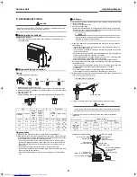
Page 5: ...e Water from the Outdoor Unit Install 5 waterproof rubber caps and the drain nipple to drain off the water from the outdoor unit Seal the knock out holes and screw thread areas tightly using a silicon adhesive or a caulking compound Use a drain pan to apply a centralized drain Installation in Regions with Snowfall and Cold Temperatures Do not use waterproof rubber caps or a drain nipple If you nee...

Page 6: ... in then tighten the nut If you find air is not taken in make sure that the charge hose is connected to the port s securely Perform extraction for about 40 minutes and make sure that the compound pressure gauge reading is 101kPa 76cmHg If the compound pressure gauge reading is not 101kPa 76cmHg there is a possibility air is being taken in from the port s Make sure that the charge hose is connected...

Page 7: ...Leak Inspection Perform a gas leak inspection for the flare nut connections valve stem connection and service port cap without fail Use a leak detector exclusively manufactured for R410A Performing Additional Installation of an Indoor Unit 1 Collect refrigerant from the outdoor unit 2 Turn off the circuit breaker 3 Perform additional installation referring to the procedure from Refrigerant Piping ...

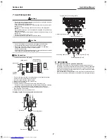
Page 8: ...ion may cause a failure 1 Detach the front panel from the outdoor unit 2 Remove the cord clamp 3 Connect the wires for the power source and each indoor unit Connect the connecting cable to the terminal as identified by the matching numbers on the terminal block of the indoor and the outdoor unit 4 Fix the wiring connections for the power source and each indoor unit securely using a cord clamp 5 At...

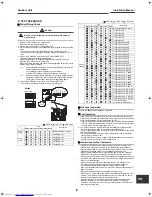
Page 9: ...ed to the other units When you start running the indoor unit or change the operation mode the unit starts running after 3 minutes This is due to the protection function of the unit not a malfunction When the external temperature becomes low the pre heating of the compressor starts to protect it Keep the circuit breaker on for use The electricity consumption during pre heating is about 100W If the ...

Page 10: ...EG44206701 ...

Reviews: