


– 94 –
No.
3
Part name
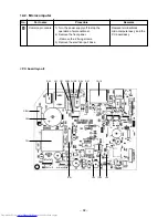
Inverter
assembly
Procedure
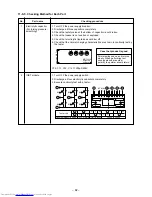
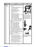
1. Detachment
1) Perform work of items 1. of
1
and
2
.
2) Remove screw (ST1TØ4 × 10L 1 pc.) of
the upper part of the front cabinet.
• If removing the inverter cover in this
condition, P.C. board can be checked.
• If there is no space in the upper part of
the upper cabinet, perform work of
2
.
Be careful to check the inverter because
high-voltage circuit is incorporated in it.
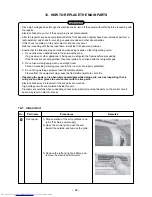
3) Perform discharging by connecting
,
polarity by discharging resistance (approx.
100
Ω
, 40W) or plug of soldering iron to
,
terminals of the C15 (printed “CAUTION
HIGH VOLTAGE” is attached.) electrolytic
capacitor (500µF) on P.C. board.
Be careful to discharge the capacitor
because the electrolytic capacitor cannot
naturally discharge and voltage remains
according to trouble type in some cases.
NOTE :
This capacitor is one with mass capacity.
Therefore, it is dangerous that a large
spark generates if short-circuiting be-
tween
,
polarity with screwdriver,
etc. for discharging.
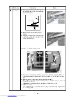
4) Remove screw (ST1TØ4 × 10L 1 pc.)
fixing the main body and the inverter box.
5) Remove various lead wires from the holder
at upper part of the inverter box and wiring
holder at right side of the terminal block.
6) Remove the lead wire from the bundled
part at left side of the terminal block.
7) Pull the inverter box upward.
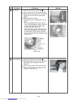
8) Disconnect connectors of various lead
wires.
Remarks
The connector is one with lock, so
remove it while pushing the part
indicated by an arrow.
Adjust length of every lead wires
other than complete and case
thermo., and bundle them.
Inverter cover
P. C. board
(Soldered surface)
Discharging position
(Discharging period
10 seconds or more)
Plug of
soldering
iron
P.M.V. coil
(A, B, and C rooms)
Holder
TO sensor
TGa, TGb, TGc
sensor
Summary of Contents for RAS-3M23GACV-E
Page 99: ... 99 MCC 1438 ...
Page 100: ... 100 MCC 818 ...


