background image

6

EN

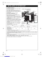
• A place which provides enough space around the outdoor 

unit as shown in the diagram.

• A place which can bear the weight of the outdoor unit and 

does not allow an increase in noise level and vibration.

• A place where the operation noise and discharged air do not 

disturb neighbors.

• A place which is not exposed to a strong wind.
• A place free of combustible gases.
• A place which does not block a passageway.
• When the outdoor unit is to be installed in an elevated 

position, be sure to secure its feet.

• Piping connections to the outdoor unit should be arranged in 

the sequence A, then B, C, starting from the bottom. (For 
each piping connection, the gas pipe is on the bottom and the 
liquid pipe on top.)

• When multiple indoor units are to be connected to the 

outdoor unit, make sure the ends of the pipes and wires from 
each indoor unit are connected to the outdoor unit correctly. 
(Problems caused by indoor units being connected to the 
outdoor unit incorrectly are very common in multiple-unit 
installations.)

• The length and height differences of the connecting pipes 

between the indoor and outdoor units must be within the 
ranges indicated below.

Allowable piping length and height difference

* Connect two or more indoor units to the 3M18.

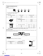
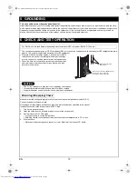
• If the outdoor unit is to be mounted on a wall, make sure the platform supporting it is sturdy enough. 

The platform should be designed and manufactured to maintain its strength over a long period of time, and sufficient consideration 
should be given to ensuring that the outdoor unit will not fall. 

• When the outdoor unit is to be mounted high on a wall, take particular care to ensure that parts do not fall, and that the installer is 

protected.

• When doing installation work at ground level, it is usual to make wiring and pipe connections to the indoor units, first, and then to 

make connections to the outdoor unit.  
However, if outdoor work is difficult it is possible, instead, to make changes to the procedure. 
For example, by making adjustments to the wiring and piping lengths on the inside (rather than the outside).

• A place where the drain water does not cause any problems.

4 INSTALLATION OF OUTDOOR UNIT

Installation Location

Outdoor unit

Piping length

Height difference

Minimum for 1 unit

Maximum for 1 unit

Maximum for 

total of 3 units

RAS-3M18SAV-E

2 m

20 m

50 m

10 m

RAS-3M18SACV-E

RAS-3M23GACV-E

40 m

100 mm or more 
from wall

250 mm or 
more from 
wall

50 mm or 
more from wall

200 mm or more

Extension drain hose

80 mm or more only 
when unobstructed to 
the front and both sides

In principle, 
leave open

When installing the 
outdoor unit, leave open 
in at least two of 
directions (A), (B), (C) 
and (D) shown in the 
right figure.

Ensure sufficient space 
to allow drainage

(A)

(B)

(C)

(D)

power 
cord

As shown in the 
figure, position 
power cord and 
connecting 
cable 
downward, and 
lead out along 
piping 
connection port.

Installation diagram of outdoor units

Item

01_OutdoorInstallation_EN.fm  Page 6  Monday, February 5, 2007  4:11 PM

Summary of Contents for RAS-3M18SACV-E

Page 1: ... КОНДИЦИОНЕР МУЛЬТИ РАЗДЕЛИТЕЛЬНОГО ТИПА Для общего бытового использования Outdoor Unit Unité extérieure Außengerät Unità esterna Unidad exterior Εξωτερική µονάδα Unidade exterior Utomhusenhet Наружный блок RAS 3M18SAV E RAS 3M18SACV E RAS 3M23GACV E Please read this installation manual carefully before installing the air conditioner Veuillez lire attentivement ce manuel avant d installer le clima...

Page 2: ...LA UNIDAD EXTERIOR 6 5 CONEXIÓN A TIERRA 12 6 COMPROBACIÓN Y OPERACIÓN DE PRUEBA 12 7 FUNCIÓN PRÁCTICA 14 1 ΠΡΟΦΥΛΑΞΕΙΣ ΑΣΦΑΛΕΙΑΣ 1 2 ΠΡΟΑΙΡΕΤΙΚΑ ΑΝΤΑΛΛΑΚΤΙΚΑ ΕΞΑΡΤΗΜΑΤΑ ΚΑΙ ΕΡΓΑΛΕΙΑ 3 3 ΠΟΙΑ ΜΟΝΤΕΛΑ ΜΠΟΡΟΥΝ ΝΑ ΣΥΝ ΥΑΣΤΟΥΝ 5 4 ΕΓΚΑΤΑΣΤΑΣΗ ΕΞΩΤΕΡΙΚΗΣ ΜΟΝΑ ΑΣ 6 5 ΓΕΙΩΣΗ 12 6 ΕΛΕΓΧΟΣ ΚΑΙ ΟΚΙΜΗ ΛΕΙΤΟΥΡΓΙΑΣ 12 7 ΧΡΗΣΙΜΕΣ ΛΕΙΤΟΥΡΓΙΕΣ 14 1 PRECAUÇÕES DE SEGURANÇA 1 2 PEÇAS OPCIONAIS ACESSÓRIOS E FERRAMEN...

Page 3: ...t water dust former refrigerant or refrigeration machine oil does not enter the new type refrigerant R410A air conditioner circuit To prevent mixing of refrigerant or refrigerating machine oil the sizes of connecting sections of charging port on main unit and installation tools are different from those of the conventional refrigerant units Accordingly special tools are required for the new refrige...

Page 4: ...AUSING THE PRESSURE INSIDE THE REFRIGERATION CYCLE TO RISE TO AN ABNORMALLY HIGH LEVEL AND POSSIBLY RESULTING IN RUPTURE INJURY ETC WHEN CARRYING OUT THE PUMP DOWN WORK SHUT DOWN THE COMPRESSOR BEFORE DISCONNECTING THE REFRIGERANT PIPE DISCONNECTING THE REFRIGERANT PIPE WITH THE SERVICE VALVE LEFT OPEN AND WITH THE COMPRESSOR STILL OPERATING WILL CAUSE AIR ETC TO BE SUCKED IN RAISING THE PRESSURE ...

Page 5: ...ecure the outdoor unit with the attachment bolts and nuts if the unit is likely to be exposed to a strong wind Use φ8 mm or φ10 mm anchor bolts and nuts If it is necessary to drain the defrost water attach drain nipple to the base plate of the outdoor unit before installing it Accessory and Installation Parts Part No Part name Q ty Part No Part name Q ty a Outdoor unit installation manual x 1 c Dr...

Page 6: ...e been changed Charge hose In order to increase pressure resisting strength hose materials and port sizes have been changed to 1 2 UNF 20 threads per inch When purchasing a charge hose be sure to confirm the port size Electronic balance for refrigerant charging As working pressure is high and gasification speed is fast it is difficult to read the indicated value by means of charging cylinder as ai...

Page 7: ...AS B10SKVP E RAS M10GKV E RAS M10SKV E RAS M10GDV E RAS M10SMUV E Outdoor unit for combination RAS 3M18SAV E Cooling only Indoor unit specification High Wall Type Slim Duct Type 4 way Air Discharge Cassette Type With air purifying unit Without air purifying unit DAISEIKAI 2 DAISEIKAI 3 16 class RAS M16GKCVP E RAS M16SKCVP E RAS M16GKCV E RAS M16SKCV E RAS M16GDCV E RAS M16SMUCV E 13 class RAS M13G...

Page 8: ... manufactured to maintain its strength over a long period of time and sufficient consideration should be given to ensuring that the outdoor unit will not fall When the outdoor unit is to be mounted high on a wall take particular care to ensure that parts do not fall and that the installer is protected When doing installation work at ground level it is usual to make wiring and pipe connections to t...

Page 9: ...stalled refer to the installation diagram of the indoor and outdoor units Check that the outdoor unit is horizontal and route the drain hose at a downward sloped angle with very little slack to the hose CAUTION 1 Install the outdoor unit in a location where there are no obstructions near its air intake or air outlet 2 When the outdoor unit is installed in a place that is always exposed to strong w...

Page 10: ...gerant Piping Connection Outer diameter of copper pipe R410A tool used Conventional tool used 6 35 0 to 0 5 1 0 to 1 5 9 52 0 to 0 5 1 0 to 1 5 12 7 0 to 0 5 1 0 to 1 5 Outer diameter of copper pipe R410A 6 35 1 5 to 2 0 9 52 1 5 to 2 0 12 7 2 0 to 2 5 Outer diameter of copper pipe B R410A R22 6 35 9 1 9 0 9 52 13 2 13 0 12 7 16 6 16 2 CAUTION Do not apply excessive force Otherwise the nut may bre...

Page 11: ...ort of the gas side packed valve 2 Connect the charge hose to the port of the vacuum pump 3 Open fully the low pressure side handle of the gauge manifold valve 4 Operate the vacuum pump to begin evacuating Perform evacuating for about 15 minutes if the piping length is 20 meters 15 minutes for 20 total meters assuming a pump capacity of 27 liters per minute Confirm that the compound pressure gauge...

Page 12: ...ower cord and the connecting cable with the cord clamp 6 Attach the electric parts cover and the valve cover on the outdoor unit Stripping length of connecting cable 3 unit A B C Multi CAUTION IMPORTANT POINTS FOR PIPING WORK 1 Prevent dust and moisture from entering the pipes 2 Tighten connections carefully between pipes and unit 3 Evacuate the air in the connecting pipes using a VACUUM PUMP 4 Ch...

Page 13: ...07RN F or 60245IEC66 1 0 mm2 CAUTION Incorrect wiring connection may cause electrical parts to burn out Be sure to comply with local regulations codes when running the wire from outdoor unit to indoor unit Size of wire and wiring method etc Every wire must be securely connected If incorrect or incomplete wiring is carried out fire or smoke may result Prepare the power supply for the exclusive use ...

Page 14: ...s leaks with a leak detector or soap water Make sure that the wiring and piping for each room have the same alphabetical code A B C Connect and secure the power cord Use the power cord cables with thickness type and protective devices specified in this manual Insulate the unused cords conductors with PVC tape 1 Turn on the power breaker 2 Open the valve cover and the electric parts cover of the ou...

Page 15: ...een determined connect the miswiring check connector For this outdoor unit self miswiring mis piping checks are possible using the five LEDs 1 Yellow 4 Red LEDs D800 to D804 are provided on the inverter P C board Miswiring mis piping check by LED Indication LED D800 D801 D802 D803 D804 Description Normal operation no error During check Checking A unit Checking B unit Checking C unit Check results ...

Page 16: ...le on current detecting circuit 17 OUTDOOR CONDENSOR PIPE TEMPERATURE SENSOR TE fault 1 18 SUCTION PIPE TEMPERATURE SENSOR TS fault 1 18 DISCHARGE PIPE TEMPERATURE SENSOR TD fault 19 Trouble on outdoor fan 1A OUTDOOR TEMPERATURE SENSOR TO fault 1B Trouble on compressor system 1C GAS SIDE PIPE TEMPERATURE SENSOR a TGa fault 1C GAS SIDE PIPE TEMPERATURE SENSOR b TGb fault 1C GAS SIDE PIPE TEMPERATUR...

Page 17: ... darauf dass kein Wasser Staub altes Kältemittel oder altes Kälteanlagenöl in den Kühlkreislauf des Klimagerät mit dem neuen Kältemittel R410A gerät Damit es nicht zu einer Vermischung von Kältemittel und Kälteanlagenöl kommt haben die Anschlüsse an den Einfüllöffnungen des Hauptgeräts bzw an den Installationswerkzeugen eine andere Größe als bei herkömmlichen Kältemitteln Aus diesem Grund sind für...

Page 18: ...GSGEFAHR USW ACHTEN SIE BEIM EVAKUIEREN DARAUF DEN KOMPRESSOR ABZUSCHALTEN BEVOR SIE DAS KÄLTEMITTELROHR ABTRENNEN FALLS DAS KÄLTEMITTELROHR BEI OFFENEM SERVICEVENTIL UND WEITERHIN IN BETRIEB BEFINDLICHEM KOMPRESSOR ABGETRENNT WIRD LUFT USW EINGESAUGT SO DASS DER DRUCK IM KÄLTEKREISLAUF ÜBERMÄSSIG ANSTEIGT WAS ZU PLATZEN VERLETZUNGEN USW FÜHREN KANN WARNUNG Dieses Gerät darf niemals so verändert w...

Page 19: ... mit den Befestigungsschrauben und Muttern falls es starkem Wind ausgesetzt sein könnte Verwenden Sie Ankerschrauben und Muttern mit φ8 mm oder φ10 mm Falls das Ablassen von Tauwasser erforderlich ist bringen Sie vor der Installation einen Ablaufnippel in die Grundplatte des Außengeräts an Zubehör und Installationsteile Teile Nr Bauteilname Menge Teile Nr Bauteilname Menge a Einbauanleitung für da...

Page 20: ... zu erhöhen wurden die Schlauchmaterialien und die Anschlussgrößen geändert in 1 2 UNF Feingewinde 20 Gewindedrehungen pro Zoll Überprüfen Sie beim Kauf eines Einfüllschlauchs unbedingt den Anschlussdurchmesser Elektronisches Dosiergerät zum Befüllen des Kältemittels Wegen des hohen Drucks und der schnellen Gasbildung lässt sich der am Einfüllzylinder angezeigte Wert nur schwer lesen da es zur Bla...

Page 21: ... Klasse 10 RAS B10GKVP E RAS B10SKVP E RAS M10GKV E RAS M10SKV E RAS M10GDV E RAS M10SMUV E Außengerät zum Kombinieren RAS 3M18SAV E Nur Kühl betrieb Spezifikation Innenraum gerät Hochwandgerät Flaches Kanalgerät 4 Wege Kassettengerät Mit Luftreinigungseinheit Ohne Luftreinigungseinheit DAISEIKAI 2 DAISEIKAI 3 Klasse 16 RAS M16GKCVP E RAS M16SKCVP E RAS M16GKCV E RAS M16SKCV E RAS M16GDCV E RAS M1...

Page 22: ...ern Sie sich dass die tragende Plattform stabil genug ist Die Plattform sollte so konstruiert und gefertigt sein dass ihre Festigkeit über lange Zeit erhalten bleibt Außerdem muss sichergestellt sein dass das Außengerät nicht herunterfallen kann Wenn das Außengerät hochliegend an einer Wand montiert werden soll muss sichergestellt sein dass keine Teile herunterfallen können und dass der Monteur vo...

Page 23: ...aagerecht installiert ist verlegen Sie den Ablaufschlauch mit Gefälle und achten Sie darauf dass der Schlauch nur sehr wenig durchhängt VORSICHT 1 Montieren Sie das Außengerät an einer Stelle an der sich in der Nähe von Lufteinlass und Luftauslass keine Hindernisse befinden 2 Wenn das Außengerät an einer Stelle montiert wird die starken Windeinwirkungen ausgesetzt ist z B in Meeresnähe oder in den...

Page 24: ... Anschließen der Kältemittelleitungen Außendurchmesser Kupferrohr Bei Verwendung von R410A Werkzeug Bei Verwendung von herkömmlichem Werkzeug 6 35 0 bis 0 5 1 0 bis 1 5 9 52 0 bis 0 5 1 0 bis 1 5 12 7 0 bis 0 5 1 0 bis 1 5 Außendurchmesser Kupferrohr R410A 6 35 1 5 bis 2 0 9 52 1 5 bis 2 0 12 7 2 0 bis 2 5 Außendurchmesser Kupferrohr B R410A R22 6 35 9 1 9 0 9 52 13 2 13 0 12 7 16 6 16 2 VORSICHT ...

Page 25: ...schlauch an die Vakuumpumpe an 3 Öffnen Sie die Lo Schraube am Manometerventil der Unterdruckseite vollständig 4 Starten Sie die Vakuumpumpe um mit dem Evakuieren zu beginnen Evakuieren Sie bei einer Rohrlänge von 20 m etwa 15 Minuten lang 15 Minuten für insgesamt 20 Meter bei einer angenommenen Pumpleistung von 27 Litern pro Minute Vergewissern Sie sich dass der abgelesene Wert bei 101 kPa 76 cmH...

Page 26: ... Anschlusskabel mit der Zugsicherung 6 Bringen Sie die Abdeckung der elektrischen Anschlüsse und die Ventilabdeckung wieder am Außengerät an Länge der zu entfernenden Kabelisolierung 3 Geräte A B C Multi VORSICHT WICHTIGE HINWEISE FÜR DIE ROHRARBEITEN 1 Staub und Feuchtigkeit dürfen nicht in die Rohre eindringen 2 Ziehen Sie die Rohrverschraubungen vorsichtig fest zwischen Rohren und Gerät 3 Sauge...

Page 27: ...EC66 1 0 mm2 VORSICHT Eine falsche Verdrahtung kann zum Durchbrennen elektrischer Teile führen Bei der Verdrahtung von Innenraum und Außengerät sind unbedingt die örtlichen Vorschriften zu befolgen Kabelquerschnitt Kabelführung usw Jeder Leiter muss sicher angeschlossen sein Bei falsch oder unvollständig ausgeführter Verdrahtung können Brände oder Rauchentwicklung verursacht werden Sorgen Sie dafü...

Page 28: ...ode besitzen A B C Schließen Sie das Netzkabel an und sichern Sie es Verwenden Sie nur Netzkabel deren Querschnitt Typ und Schutzvorrichtungen den Angaben in dieser Anleitung entsprechen Isolieren Sie nicht verwendete Kabel Adern mit PVC klebeband 1 Schalten Sie den Schutzschalter ein 2 Öffnen Sie die Ventilabdeckung und die Abdeckung der elektrischen Anschlüsse des Außengeräts 3 Schalten Sie das ...

Page 29: ...n Sie den Prüfstecker an Bei diesem Außengerät ist eine Selbstüberprüfung auf Kabel oder Leitungsanschlussfehler anhand der fünf LEDs möglich 1 gelbe 4 rote LEDs Die LEDs D800 bis D804 befinden sich an der PC Konsole des Inverters Prüfen auf Kabel oder Leitungsanschlussfehler über die LED Anzeige LED D800 D801 D802 D803 D804 Beschreibung Normalbetrieb kein Fehler Während der Prüfung Überprüfung Ge...

Page 30: ...Problem in Stromdetektorschaltung 17 Fehler am TEMPERATUR SENSOR TE KONDENSATORLEITUNG AUSSEN 1 18 Fehler am SAUGROHR TEMPERATUR SENSOR TS 1 18 Fehler am DRUCKROHR TEMPERATUR SENSOR TD 19 Problem am Außenventilator 1A Fehler am AUSSENTEMPERATUR SENSOR TO 1B Problem im Kompressorsystem 1C Fehler am ROHRTEMPERATUR SENSOR a GASSEITE TGa 1C Fehler am ROHRTEMPERATUR SENSOR b GASSEITE TGb 1C Fehler am R...

Page 31: ...EG20408001 a 00_OutdoorInstallation_BCO fm Page 4 Friday March 23 2007 3 02 PM ...

Reviews: