– 1 –
FILE NO. SVM-02009
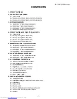
CONTENTS
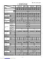
1. SPECIFICATIONS
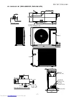
2. CONSTRUCTION VIEWS
2-1 Indoor Unit
2-2 Outdoor Unit (RAS-18UAH-ES, RAS-18UA-ES)
2-3 Outdoor Unit (RAS-24UAH-ES, RAS-24UA-ES)
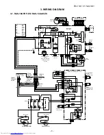
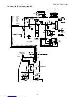
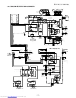
3. WIRING DIAGRAM
3-1 RAS-18UFHP-ES / RAS-18UAH-ES
3-2 RAS-18UFP-ES / RAS-18UA-ES
3-3 RAS-24UFHP-ES / RAS-24UAH-ES
3-4 RAS-24UFP-ES / RAS-24UA-ES
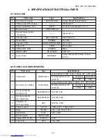
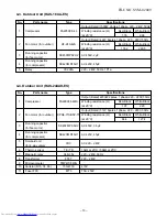
4. SPECIFICATION OF ELECTRICAL PARTS
4-1 Indoor Unit
4-2 Outdoor Unit (RAS-18UAH-ES)
4-3 Outdoor Unit (RAS-18UA-ES)
4-4 Outdoor Unit (RAS-24UAH-ES)
4-5 Outdoor Unit (RAS-24UA-ES)
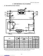
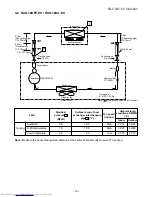
5. REFRIGERATION CYCLE DIAGRAM
5-1 RAS-18UFHP-ES / RAS-18UAH-ES
5-2 RAS-18UFP-ES / RAS-18UA-ES
5-3 RAS-24UFHP-ES / RAS-24UAH-ES
5-4 RAS-24UFP-ES / RAS-24UA-ES
6. CONTROL BLOCK DIAGRAM
6-1 RAS-18UFHP-ES, RAS-24UFHP-ES
6-2 RAS-18UFP-ES, RAS-24UFP-ES
7. OPERATION DESCRIPTION
7-1 Outline of Air Conditioner Control
7-2 Description of Operation Circuit
7-3 Hi POWER Mode
7-4 High-Temperature Limit Control
7-5 Low-Temperature Limit Control
7-6 Defrosting Operation
7-7 Auto Restart Function
7-8 Filter Check Lamp
8. INSTALLATION PROCEDURE
8-1 Safety Cautions
8-2 Installation Diagram of Indoor and Outdoor Units
8-3 Installation
8-4 Indoor Unit
8-5 Outdoor unit
8-6 How to Set Remote Control Selector Switch
8-7 How to Use Drain Pump Kit of Option
8-8 Others

