


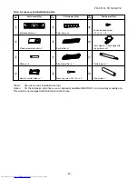


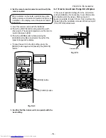

8-2. Installation Diagram of Indoor and Outdoor Units
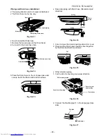
For installation of the indoor unit, use the paper pattern, which is inside the package box cover.
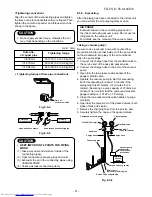
Before install the wireless
remote control
With the remote control cover
open, load the batteries supplied
correctly, observing their polarity.
22222 Wireless remote control
33333 Batteries
Cover
Pipe
shield
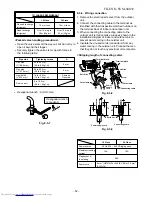
(Under Ceiling Installation)
70 mm or more
200
mm
or more
200 mm or more
Insulate the refrigerant
pipes separately with
insulation, not together.
6 mm thick heat resisting
polyethylene foam
(Console Installation)
6
Zeolite filter
7
Bioenzyme filter
Air filter
5
Filter frame
2
Wireless remote
control
4
Remote control
holder
9
Pan head
wood screw
200 mm
or more
8
Mounting
screw
Hook
70
m
m
o
r m
ore
200 mm
or more
1
Installation
plate
100 mm
or m
ore
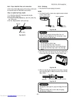
Vinyl tape Apply
after carrying out
a drainage test
Saddle
Extension
drain hose
(Option:
RB
-
821SW)
Extension
drain hose
(Option:
RB
-
821SW)
Electric
parts
cover
Electric
parts cover
18 Class
Heat pump
600
mm
or
mo
re
24 Class
18 Class
Cooling only
600 mm or more
600 mm
or more
100 m
m or
mor
e
600 mm or more
600
mm
or
mo
re
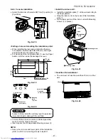
Loop the connective cable
(about 100 mm in diameter and 300
−
350 mm long).
Loop the connective cable
(about 100 mm in diameter and 300
−
350 mm long).
100 mm
or more
600 mm
or more
100 mm
or more
600 mm
or more
FILE NO. SVM-04032
– 40 –


