–
110
–
No.
Part name
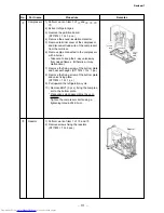
Side cabinet
Procedure
1. Side cabinet (right)
1) Perform step 1 in
and all the steps in
.
2) Remove the fixing screw (ST1TØ4 ×
10
L
4
pcs.) used for securing the side
cabinet to the bottom plate and valve
fixing panel.
2. Side cabinet (left)
1) Perform step 1 in
.
2) Remove the fixing screw (ST1TØ4 ×
10
L
1 pc.) used to secure the side cabinet
(left) onto the heat exchanger.
3) Remove the fixing screw (ST1TØ4 ×
10
L
2 pc
s
.) used for securing the side cabinet
to the bottom plate and heat exchanger.
Remarks
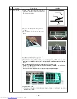
Detail A
Detail B
Detail C
1) Perform work of item 1 of
and
.
2) Remove the flange nut fixing the fan motor
and the propeller.
• Flange nut is loosened by turning clock-
wise. (To tighten the flange nut, turn
counterclockwise.)
3) Remove the propeller fan.
4) Disconnect the connector for fan motor
from the inverter.
5) Remove the fixing screws (
4
pc
s
.) holding
by hands so that the fan motor does not
fall.
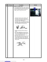
* Precautions when assembling the fan
motor
Tighten the flange nut using a tightening
torque of 4.9 N•m.
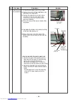
Fan motor
Hook the claw noto
the bottom plate
The back body section hooked
onto the bottom plate here.
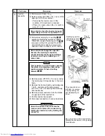
Propeller fan
Fan motor
Flange nut


