– 3 –
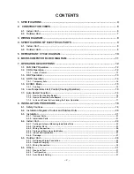
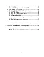
9. TROUBLESHOOTING CHART ..................................................................................... 32
9-1.
What to be Prechecked First .................................................................................................. 32
9-1-1. Power Supply Voltage ........................................................................................................................... 32
9-1-2. Incorrect Cable Connection between Indoor and Outdoor Units ..................................................... 32
9-1-3. Misleading but Good Operations .........................................................................................................33
9-2.
Primary Judgement of Trouble Sources ............................................................................... 34
9-2-1. Role of Indoor Unit Controller .............................................................................................................. 34
9-2-2. Display of Abnormalities and Judgement of the Abnormal Spots ................................................... 34
9-3.
Troubleshooting Flowcharts ................................................................................................... 38
9-3-1. Power can not be Turned on ................................................................................................................38
9-3-2. Power can not be Turned on after Replacing Indoor PC Board ....................................................... 39
9-3-3. Outdoor Unit does not Operate ...........................................................................................................39
9-3-4. Only Compressor does not Operate ................................................................................................... 40
9-3-5. Only Outdoor Fan does not Operate ................................................................................................... 41
9-3-6. Only the Indoor Fan does not Operate ................................................................................................ 42
9-4.
How to Check the Remote Control (Including the Indoor PC Board) ................................ 43
9-4-1. How to Check the PC Board ................................................................................................................. 44
9-4-2. PC Board Layout ...................................................................................................................................46
9-4-3. How to Reduce the Operation Time of the Anti-Restart Timer .........................................................47
10. PART REPLACEMENT ................................................................................................. 48
10-1. Indoor Unit ................................................................................................................................ 48
10-2. Microcomputer ......................................................................................................................... 50
10-3. Outdoor Unit ............................................................................................................................. 51
11. CAUTIONS ON REPLACEMENT OF PC BOARD ASSEMBLY .................................... 52
12. EXPLODED VIEWS AND PARTS LIST ........................................................................ 53
12-1. Indoor Unit (1) ........................................................................................................................... 53
Indoor Unit (2) ........................................................................................................................... 54
12-2. Outdoor Unit ............................................................................................................................. 55
Summary of Contents for RAS-10SA-E
Page 46: ... 46 9 4 2 PC Board Layout Bottom View Top View ...
Page 56: ......


