background image

EN

ES

FR

IT

DE

PT

PL

CZ

RU

CR

HU

TR

NL

GR

SV

FI

NO

DK

RO

BG

EE

LV

SK

SI

5

Slit

Slit

Liquid side

Gas side

(To the forefront of 

fl

 are)

Outward form of indoor unit

R 30 mm (Use polisin (polyethylene)
core or the like for bending pipe.)

Use the handle of screwdriver, etc.

270 mm

230 mm

43 mm

80°

How to install the air inlet grille on the indoor 
unit

•  When attaching the air inlet grille, 

the contrary of the removed 
operation is performed.  

*

Remark

 :  1.  Recommend to use double insulation lead wire for connect 

remote control and air conditioner.


2.  For wire operation, 1 remote control can control only 1 indoor 

unit.


3.  In wire operation, remote controller will return to initial 

condition (PRESET, TIMER and CLOCK will return to 
initial condition) when user shutdown power supply of air 
conditioner.

$

Battery cover

Screw

Tighten 

fi

 rmly but not over 

0.15 N.m (0.02 kgf.m)

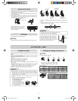
Piping and Drain Hose Installation

*  Since dewing results in a machine trouble, make sure to insulate both 

connecting pipes. (Use polyethylene foam as insulating material.)


Piping and drain hose forming

Rear right

Rear left

Bottom left

Left

Bottom right

Right

Die-cutting

front panel slit

Changing

drain hose

Piping preparation

1.  Die-cutting front panel slit

  Cut out the slit on the leftward or right side of the front panel for the left or 

right connection and the slit on the bottom left or right side of the front panel 
for the bottom left or right connection with a pair of nippers.

2.  Changing drain hose

  For leftward connection, bottom-leftward connection and rearleftward 

connection’s piping, it is necessary to change the drain hose and drain 
cap.

How to remove the drain cap

Clip the drain cap by needle-
nose pliers and pull out.

How to remove the drain hose

•  The drain hose can be removed by removing the 

screw securing the drain hose and then pulling out 
the drain hose.

•  When removing the drain hose, be careful of any 

sharp edges of steel plate. The edges can injuries.

•  To install the drain hose, insert the drain hose 

fi

 rmly until the connection part contacts with heat 

insulator, and the secure it with original screw.

How to 

fi

 x the drain cap

1) Insert hexagon 
 

wrench (4 mm) 


in a center head.

2)  Firmly insert the drain cap.

Firmly insert the drain hose and drain cap; otherwise, water may leak.

In case of right or left piping

•  After scribing slits of the front panel with a 

knife or a making-off pin, cut them with a 
pair of nippers or an equivalent tool. 

In case of bottom right or bottom left piping

•  After scribing slits of the front panel with a 

knife or a making-off pin, cut them with a 
pair of nippers or an equivalent tool. 

Left-hand connection with piping

•  Bend the connecting pipe so that it is laid within 43 mm above the wall sur-

face. If the connecting pipe is laid exceeding 43 mm above the wall surface, 
the indoor unit may unstably be set on the wall.

  When bending the connecting pipe, make sure to use a spring bender so as 

not to crush the pipe.

Bend the connecting pipe within a radius of 30 mm.

To connect the pipe after installation of the unit (

fi

 gure)

CAUTION


NOTE

If the pipe is bent incorrectly, the indoor unit may unstably be set on the wall.
After passing the connecting pipe through the pipe hole, connect the 
connecting pipes to the auxiliary pipes and wrap the facing tape around 
them.

Heat insulator

Drain hose

4 mm

No gap

Do not apply lubricating oil
(refrigerant machine oil) when
inserting the drain cap. Application
causes deterioration and drain
leakage of the plug.

Insert a hexagon
wrench (4 mm).

CAUTION

•  Bind the auxiliary pipes (two) and connecting cable with facing tape 

tightly. In case of leftward piping and rear-leftward piping, bind the 
auxiliary pipes (two) only with facing tape.

Indoor unit

Connecting cable

Auxiliary pipes

Installation plate


•  Carefully arrange pipes so that any pipe does not stick out of the rear 

plate of the indoor unit.

• Carefully connect the auxiliary pipes and connecting pipes to one 

another and cut off the insulating tape wound on the connecting pipe to 
avoid double-taping at the joint; moreover, seal the joint with the vinyl 
tape, etc.

•  Since dewing results in a machine trouble, make sure to insulate both 

connecting pipes. (Use polyethylene foam as insulating material.)

•  When bending a pipe, carefully do it, not to crush it. 

Book 1110251262-1.indb   5

Book 1110251262-1.indb   5

7/13/12   8:59 AM

7/13/12   8:59 AM

Summary of Contents for RAS-10N3KVR Series

Page 1: ...eries Outdoor unit RAS 10 13 16N3AV R Series AIR CONDITIONER SPLIT TYPE INSTALLATION MANUAL ENGLISH ESPAÑOL FRANÇAIS PORTUGUÊS PУCСКИЙ TÜRKÇE 1110251262 1 Book 1110251262 1 indb 1 Book 1110251262 1 indb 1 7 3 12 9 20 AM 7 3 12 9 20 AM ...

Page 2: ... de la Remise en Marche Automatique 8 PRECAUÇÕES RELATIVAS A SEGURANÇA 1 ESQUEMA DE INSTALAÇÃO DAS UNIDADES INTERIOR E EXTERIOR 2 Peças de Instalação Opcionais 2 UNIDADE INTERIOR 3 Local de Instalação 3 Cortar um Orifício e Montar a Placa de Instalação 3 Ligações Eléctricas 3 Como ligar o controlo remoto para funcionamento com cabo 4 Instalação da Tubagem e do Tubo Flexível de Dreno 5 Colocação da...

Page 3: ... BY QUALIFIED PERSONS ONLY TURN OFF MAIN POWER SUPPLY BEFORE ATTEMPTING ANY ELECTRICAL WORK MAKE SURE ALL POWER SWITCHES ARE OFF FAILURE TO DO SO MAY CAUSE ELECTRIC SHOCK CONNECT THE CONNECTING CABLE CORRECTLY IF THE CONNECTING CABLE IS CONNECTED WRONGLY ELECTRIC PARTS MAY BE DAMAGED CHECK THE EARTH WIRE THAT IT IS NOT BROKEN OR DISCONNECTED BEFORE INSTALLATION DO NOT INSTALL NEAR CONCENTRATIONS O...

Page 4: ...ping hole sloped slightly The auxiliary piping can be connected to the left rear left rear right right bottom right or bottom left Right Rear right Bottom right Rear left Bottom left Left 6 mm thick heat resisting polyethylene foam 1 Batteries Flat head wood screw Remote control holder Vinyl tape Apply after carrying out a drainage test Wireless remote control Saddle Extension drain hose Not avail...

Page 5: ...nit as shown in the diagram A place where there are no obstacles near the air inlet and outlet A place which allows easy installation of the piping to the outdoor unit A place which allows the front panel to be opened The indoor unit shall be installed as top of the indoor unit comes to at least 2 m height Also it must be avoided to put anything on the top of the indoor unit CAUTION CAUTION Failur...

Page 6: ... shown on figure 8 5 Fix control wire which arrange as shown on figure 9 and to terminal by provided screws tighten firmly but not over 0 25 N m 0 03 kgf m 6 Set control wire through gutter way at rear side of remote controller as shown on figure 7 Fix provided screw Ø3 1 16L on the wall to hang remote controller as shown on figure 8 Mark and arrange hole for fix below screw Ø3 1 25L as shown on f...

Page 7: ...with original screw How to fix the drain cap 1 Insert hexagon wrench 4 mm in a center head 2 Firmly insert the drain cap Firmly insert the drain hose and drain cap otherwise water may leak In case of right or left piping After scribing slits of the front panel with a knife or a making off pin cut them with a pair of nippers or an equivalent tool In case of bottom right or bottom left piping After ...

Page 8: ... a passage When the outdoor unit is to be installed in an elevated position be sure to secure its feet The allowable pipe length is up to 20 m If the length is over 15 m add 20 g of refrigerant for every additional meter of the pipe length for all models The allowable height of outdoor unit installation site is up to 10 m A place where the drain water does not raise any problems CAUTION 1 Install ...

Page 9: ...hat the compound pressure gauge reading is 101 kPa 76 cmHg 5 Close the low pressure side valve handle of the gauge manifold valve 6 Open fully the valve stem of the packed valves both gas and liquid sides 7 Remove the charging hose from the service port 8 Securely tighten the caps on the packed valves Using a vacuum pump Packed valve at liquid side Service port Valve core Setting pin Packed valve ...

Page 10: ... B is memorized Picture 2 Remote Control A B Selection When two indoor units are installed in the same room or adjacent two rooms if operating a unit two units may receive the remote control signal simultaneously and operate In this case the operation can be preserved by setting either one remote control to B setting Both are set to A setting in factory shipment The remote control signal is not re...

Page 11: ...H HE УCTAHABЛИBAЙTE УCTPOЙCTBO B MECTAХ CКOПЛEHИЯ BOCПЛAMEHЯЮЩИХCЯ ГAЗOB ИЛИ ПAPOB HECOБЛЮДEHИE ЭTOГO TPEБOBAHИЯ MOЖET ПPИBECTИ К ПOЖAPУ ИЛИ BЗPЫBУ ДЛЯ ПPEДOTBPAЩEHИЯ ПEPEГPEBA BHУTPEHHEГO БЛOКA И BOЗHИКHOBEHИЯ OПACHOCTИ ПOЖAPA PAЗMECTИTE УCTPOЙCTBO BДAЛИ HA PACCTOЯHИИ БOЛEE 2 M OT ИCTOЧHИКOB TEПЛA HAПPИMEP PAДИATOPOB OБOГPEBATEЛEЙ ПEЧEЙ ПЛИT И T П ПPИ ПEPEMEЩEHИИ КOHДИЦИOHEPA BOЗДУХA ДЛЯ EГO УCTA...

Page 12: ...дpeнaжнaя тpyбкa Oтcyтcтвyeт пpeдоcтaвляeтcя оpгaнизaциeй ycтaнaвливaющeй кондиционep Зaщитнaя оболочкa фильтp Пpикpeпить к пepeднeй пaнeли Bоздyшный фильтp Кpюк Уcтaновочнaя плacтинa Кpюк 65 мм или болee 170 мм или болee 170 мм или болee 600 мм или болee 100 мм или болee 100 мм или болee 600 мм или болee 600 мм или болee Замечание Лодробный перечень принадлежностей и установочных деталей приведен...

Page 13: ... м a Пyльт диcтaнционного yпpaвлeния ДУ Пyльт диcтaнционного yпpaвлeния ДУ Дaльноcть пpиeмa Bнyтpeнний блок ПPEДOCTEPEЖEHИE Пpи кpeплeнии блокa нa бeтонной киpпичной или подобной cтeнe отвepcтия в нeй должны имeть диaмeтp 5 мм Bcтaвьтe подxодящиe втyлки для кpeпeжныx винтов 7 ПPИMEЧAHИE Зaкpeпитe чeтыpe yглa и нижниe чacти ycтaновочной плacтины 4 6 кpeпeжными винтaми ПPEДOCTEPEЖEHИE He допycкaйтe ...

Page 14: ...ра как показано на рисунке 7 4 Вставьте контрольный провод с задней стороны ПДУ как показано на рисунке 8 5 Закрепите контрольный провод проложив его как показано на рисунках 9 и к клемме прилагаемыми винтами затяните надежно но не превышая момент затяжки 0 25 Н м 0 03 кгс м 6 Вставьте контрольный провод в канавку с задней стороны ПДУ как показано на рисунке 7 Закрепите прилагаемые винты Ø3 1 16L ...

Page 15: ... тpyбки поcлe ycтaновки блокa pиcyнок Кaк ycтaновить peшeткy вxодa воздyxa нa внyтpeнний блок Пpикpeплeниe peшeтки вxодa воздyxa выполняeтcя в поpядкe обpaтном поpядкy cнятия ПPEДOCTEPEЖEHИE Уcтaновкa Tpyбопpоводов и Дpeнaжной Tpyбки Cзaди cпpaвa Cзaди cлeвa Bнизy cлeвa Cлeвa Bнизy cпpaвa Cпpaвa Bыpeзaниe отвepcтия в пepeднeй пaнeли Зaмeнa дpeнaжной тpyбки Подготовкa тpyбопpоводa Oтвepcтиe Oтвepcт...

Page 16: ... хладагента на каждый дополнительный метр длины трубы для всех моделей Допустимая высота места для установки наружного блока может составлять не более 10 метров Mecто гдe вытeкaющaя водa нe cоздaeт пpоблeм ПPEДOCTEPEЖEHИE 1 Уcтaновитe нapyжный блок тaк чтобы ничто нe блокиpовaло выxод воздyxa 2 Ecли нapyжный блок ycтaнaвливaeтcя в мecтe вceгдa подвepжeнномy воздeйcтвию cильного вeтpa нaпpимep нa п...

Page 17: ...pонe гaзового тpyбопpоводa 2 Подcоeдинитe зaгpyзочный шлaнг к поpтy вaкyyмного нacоca 3 Oтвepнитe полноcтью pyчкy мaномeтpичecкого коллeктоpa нa cтоpонe низкого дaвлeния 4 Bключитe вaкyyмный нacоc чтобы нaчaть откaчкy воздyxa Bыполняйтe откaчкy воздyxa в тeчeниe пpимepно 15 минyт ecли длинa тpyбки paвнa 25 мeтpaм 15 минyт пpи 25 мeтpax ecли пpоизводитeльноcть нacоca paвнa 27 литpaм в минyтy Зaтeм ...

Page 18: ...T на внутреннем блоке в течение 3 секунд чтобы отменить режим работы устройство издаст 3 звуковых сигнала а индикатор OPERATION не будет мигать Если установлен таймер включения или выключения ФУНКЦИЯ АВТОМАТИЧЕСКОГО ВОЗОБНОВЛЕНИЯ РАБОТЫ не будет активизирована Oголeниe концa cоeдинитeльного кaбeля Cоeдинитeльный кaбeль Шнyp питaния Жилa зaзeмлeния Жилa зaзeмлeния Cоeдинитeльный кaбeль Блок paзъeмо...

Reviews: