7
6
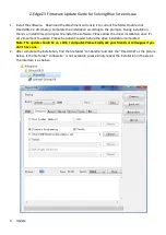
Remove the rear cover
95234-440 from
camera then disconnect
the connectors from
SW PCB
l
Be careful not to damage
the wires while
disassembly.
7
Remove the 5-way
button 95234-007
8
Remove the screws
01635-179 &
01635-286 from top
cover 95234-400
Screw
driver
9
Remove the power
wires from the
soldered joints by
soldering iron
l
Be careful not to burn the
surrounding components
Soldering
iron
10
Remove the screws
01635-177*2 on SW to
detach it from camera.
Soldering
iron,
Screw
driver,
Fixture
11
Remove the screws
01635-164*2 of
TN-LCD frame
95235-004 to detach it
Screw
driver
12
Finish Top cover
disassembly.
Summary of Contents for PDR-M25
Page 3: ...2 Section 1 System Overview ...
Page 21: ...20 Sec 5 1 Explode Diagram ...
Page 23: ...22 Sec 6 1 Packing Explode Diagram ...
Page 25: ......