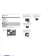
SET
TIME
TIMER SET
TEST
FILTER
RESET
TEMP.
CL
FAN
SAVE
SWING/FIX
VENT
MODE
ON / OFF
UNIT LOUVER
2
14
15
5
7
3
1
4
6
11
9
8
13
12
10
19
1816
20
21
22
17
3
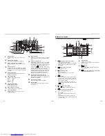
Part names and functions of the remote
controller
◆
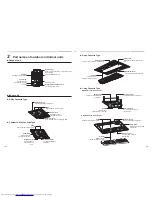
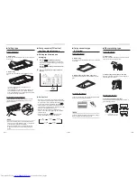
Floor Standing Concealed Type
◆
Floor Standing Type
Drain funnel (with strainer)
Accessory to be attached at the site
Air
fi
lter
Filters out dust.
(Inside the return air grille)
Metal
fi
ttings
Vertical louver
Automatically directs the air
fl
ow
horizontally at regular intervals.
Drain pan
Water collected here is drained out
through the drain pipe.
Metal
fi
ttings (left/right)
Front panel (lower)
Earth screw
Equipped on the electrical
control box.
Air intake
Air in the room is taken in
through here.
Discharge louver
Controls discharge air directions.
Earth screw
Equipped on the electrical control box.
Air
fi
lter
Filters out dust
Air intake
Air in the room is taken in through here.
Air discharge
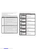
All indicators are displayed in the display example below.
Actually, only the selected options will be displayed.
•
blinks on the display of the remote controller the
fi
rst time the
power switch is turned on.
• The initial settings progress while
is blinking. Start to use the
remote controller after
has disappeared.
1
SETTING indicator
Displayed when setting the timer or other
functions.
2
Operation mode indicator
Indicates the operation mode selected.
3
Error indicator
Displayed when the protective device activates or
an error occurs.
4
Time display
Indicates time concerning the timer.
(Indicates an error code when an error occurs)
5
Timer mode indicator
Displays the timer mode.
6
Filter indicator
Reminder to clean the air
fi
lter.
7
TEST run indicator
Displayed during test run.
8
Louver position display
Indicates the louver position.
* Only for 4-way cassette, 1-way cassette, 2-way
cassette, ceiling types
Display
section
Operation
section
This remote controller can control up to 8 indoor units.
■
Display section
NOTE
The LCD may temporarily be blurred due to static electricity.
– 9 –
17-EN
18-EN


