– 25 –
49-EN
50-EN
■
Setting when connecting
indoor units to FS (Flow
Selector) unit
◆
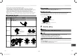
Cautions to connection of indoor
unit
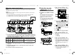
• When connecting the indoor units to a single port
type FS unit and a branch of the multi port type FS
unit, it is necessary to set up the CODE No..
Be sure to set up the CODE No. after setup of
address.
• When connecting the indoor units to a single port
type FS unit and a branch of the multi port type FS
unit, it is possible to connect with multiple groups
and connect individually.
Single port type FS unit
Piping
Control wiring
between indoor
unit and FS unit
(Within 49 ft
(15 m))
Remote control
Group control
Indoor unit
Indoor unit
Piping
Multi port type FS unit
Remote control
Group control
Indoor unit
Remote control
Group control
Single port type FS unit
Piping
Incorrect
Control wiring
between indoor
unit and FS unit
Single port type FS unit
Piping
◆
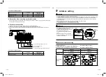
How to set up CODE No. [ 0E ]
It is necessary to set up in case of the group control.
2
4
1
3
.
5
1
Push and hold the , , and buttons at
the same time for more than 4 seconds.
•
is displayed in the UNIT No. window.
•
In this time, the fans of all the indoor units in the
group control start the fan operation.
2
Using the set temperature buttons
/
, select the CODE No. “
”.
3
Change SET DATA to “
” by the timer
buttons / .
4
Push button.
5
Push button. Then the setup
fi
nished.
◆
How to set up CODE No. [ 14 ]
It is necessary to set up group address in case of the
group control.
0 : Individual
1 : Header unit
2 : Follower unit
◆
How to set up CODE No. [ FE ]
In cases other than connecting with one indoor unit or
one group in one branching, it is necessary to set up.
• As for both single port type and multi port type,
set up CODE No. “FE” in one branching within the
range of 1~64.
This CODE No. should not be duplicate in one
system.
◆
How to set up CODE No. [ FD ]
In cases other than connecting with one indoor unit or
one group in one branching, it is necessary to set up.
0 : Heating prioritized (Factory default)
1 : Cooling prioritized
■
Resetting to factory default address
Method 1
Follow steps 1 through 11 by using a direct wired remote control (page 22) to reset line (system) address, indoor
unit addresses and group addresses to “0099”.
Method 2
Clearing all the indoor unit addresses on a single refrigerant line and reset all addresses to the factory default
settings follow the steps below:
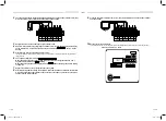
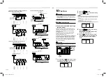
1. To turn off the refrigerant line and reset all address to the factory default settings follow the steps below:
A. On the header outdoor unit, open the connector between (U1, U2) and (U3, U4) terminals.
B. On the header outdoor, interface PC board, SW30 DIP switch 2, set to ON.
U3 U4
U1 U2
U5 U6
U1 U2
A B
U3 U4
U1 U2
U5 U6
U1 U2
A B
U3 U4
U1 U2
U5 U6
U1 U2
A B
U3 U4
U1 U2
U5 U6
U1 U2
A B
U3 U4
U1 U2
U1
U3
U2
U4
U5 U6
U1 U2
A B
Header
unit
Header
unit
Header
unit
Central control
Remote
control
Remote
control
Remote
control
Remote
control
Indoor units to have their addresses initialized
Follower unit
Follower unit
1
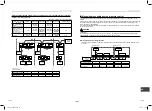
Turn on the indoor and outdoor units of the refrigerant line for which initialize the addresses to
be initialized. About one minute after turning on the power, con
fi
rm that the 7-segment display
on the header outdoor unit indicates “U.1. - - -” and operate the interface P.C. board on the
header outdoor unit of the refrigerant line as follows:
SW01
SW02
SW03
SW04
Clearable addresses
2
1
2
Confirm that the 7-segment display indicates
“A.d.buS” and turn SW04 ON for more than five
seconds.
System/indoor unit/group address
2
2
2
Confirm that the 7-segment display indicates
“A.d.nEt” and turn SW04 ON for more than five
seconds.
Central control address
2
Con
fi
rm that the 7-segment display indicates “A.d. c.L.” and set SW01, SW02 and SW03 to 1, 1, 1
respectively.
3
After a time “U.1.L08” appears on the 7-segment display if the address clearing has been
completed successfully.
4
Set the addresses again after
fi
nishing the clearance.
1122001201_EN FR.indd 25
1122001201_EN FR.indd 25
9/2/16 1:30 PM
9/2/16 1:30 PM


