209
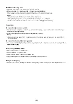
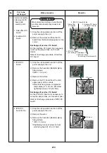
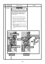
2) When pushing in the lower part,
be sure to check that the cable
is not be stretched.
5)
2)
3 Scre
Screw
3 Scre
Screw
4)
4) Fixing cla
Fixing claw
Pull out to
Pull out toward y
ard you.
ou.
3) Screw
3) Screw
Pull out toward you.
4) Fixing claw
No.
4
Part to be
exchanged
HeInverter
assembly
M
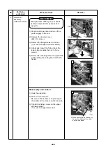
Removal of box
Work procedure
REQUIREMENT
Wear protective clothing on your hands
as other components may cause and
injury etc.
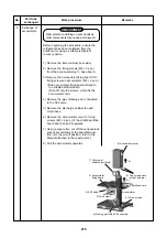
1) Stop the unit operation and turn off the
power supply to the unit.
2) Remove the inverter cover.
(M4 × 10, 2 pcs.)
3) Remove the fixing screws on the box.
(1 pc. each at upper and lower sides.)
4) Lightly push down the fixing tab at the
lower side to enable the box to be re-
moved.
5) Remove the hooking tab at the upper side
while holding the ceiling board with both
hands.
Remarks
Reassembly and cautions
1) Hook the upper tab.
2) Push in the lower part.
Be sure to check there is no pinching of
the cables at the corners on the rear side.
3) Tighten the fixing screws on the upper
and lower sides.
(1 pc. each at upper/lower part)


