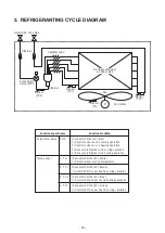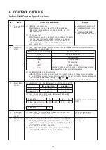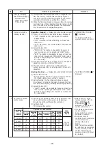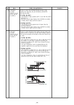
7
-1-
2
. Connection of Wireless Remote Controller
Power supply
220-240V~, 50Hz
208-230V~, 60Hz
N
L
Same as
the left
#3
A
B
U3
U4
B
A
A
B
#2
Follower unit
Indoor unit
#1 Header unit
Indoor control P.C.
board (MCC-1
696
)
Receiver and
Display P.C. board
(
WP-033
)
Louver
motor
Indoor
fan motor
CPU
RL78/G13
Driver
Buzzer
DC5V
DC12V
DC20V
Outside
output
Central control
communication circuit
Remote controller
communication circuit
Display LED
Receiver unit
Driver
Power circuit
DC280V
DC15V
Fan motor
control circuit
EEPROM
TA sensor
TC sensor
TCJ sensor
HA
Run/
Warning/
Defrost/
Thermo. ON/
COOL/HEAT/
FAN
Bus communication
circuit
Wireless remote
signal setting
(A/B)
Central control
remote controller
(Sold separately)
AC
synchronous
signal input circuit
Outdoor
unit
Same as
the left
Outdoor
unit
Outdoor Unit
Uv(
U1
)
Uv(
U2
)
Power
s
upply
Power
s
upply
Louver
motor
- 26 -
Summary of Contents for MMK- UP0301HP Series
Page 16: ...3 WIRING DIAGRAM 16 ...

