43-EN
‒
43
‒
43-EN
Installation Manual
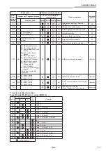
*1 Inverter quantity information
(Super Modular Multi System e and u series (SMMS-e, SMMS-u))
No.
Comp.
Inverter
Fan Inverter
Trouble
1
2
1
2
01
Comp. 1
02
Comp. 2
03
Comp. 1 + Comp. 2
08
Fan 1
09
Comp. 1 + Fan 1
0A
Comp. 2 + Fan 1
0B
Comp. 1 + Comp. 2 + Fan 1
10
Fan 2
11
Comp. 1 + Fan 2
12
Comp. 2 + Fan 2
13
Comp. 1 + Comp. 2 + Fan 2
18
Fan 1 + Fan 2
19
Comp. 1 + Fan 1 + Fan 2
1A
Comp. 2 + Fan 1 + Fan 2
1B
All
: Inverter trouble
• For details about check codes determined with an Interface P.C. board or an Inverter P.C. board, refer to the
Installation Manual of the outdoor unit.
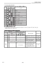
Trouble detected by central control device
Check code
Wireless remote controller
Check code name
Judging device
Central
control
device
indication
Outdoor unit 7-segment
display
Sensor block display of
receiving unit
Auxiliary code
Operation Timer Ready Flash
C05
—
—
—
Sending trouble in central control
device
Communication
Link
C06
—
—
—
Receiving trouble in central control
device
Communication
Link
C12
—
—
—
Batch alarm of general-purpose
equipment control interface
General-purpose
equipment I/F
P30
(L20)
Differs according to trouble contents of unit with occurrence of
alarm
Group control follower unit trouble
Communication
Link
—
—
(L20 is displayed.)
• Duplication addresses of indoor
units in central control device
• With the combination of air
conditioning system, the indoor
unit may detect the check code
of L20


