

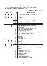


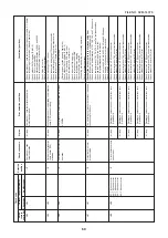
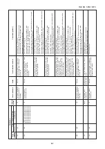


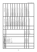


61
Chec
k code
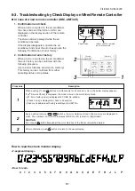
Wired remote
contr
oller
H15
H16
H25
L03
L04
Outdoor 7-segment displa
y
Chec
k code
A
uxiliar
y
code
H15
—
H16
01:
TK1 oil circuit system error
02:
TK2 oil circuit system error
03:
TK3 oil circuit system error
04:
TK4 oil circuit system error
05:
TK5 oil circuit system error
H25
—
——
L04
—
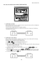
Detected position
I/F
I/F
I/F
Indoor
I/F
Chec
k code name
Outdoor unit discharge temp
. sensor (TD2)
mis
wir
ing
Oil le
vel detectiv
e
circuit system error
Outdoor unit discharge temp
. sensor (TD3)
mis
wir
ing
Duplicated indoor center units
Duplicated outdoor line address
Status
All stop
All stop
All stop
Corresponding unit only stops
.
All stop
E
rr
or detection condition
While compressor 2 is operating, the discharge temp
. (TD2) does
not r
ise up
.
Temper
ature change of
TK1 could
not be detected though compressor 1 star
ted the
oper
ation.
Temper
ature change of
TK2 could
not be detected though compressor 2 star
ted the oper
ation.
Temper
ature change of
TK3 could
not be detected though compressor star
ted the oper
ation.
Temper
ature change of
TK4 could
not be detected though compressor star
ted the oper
ation, or the
diff
erence from other
TK sensor
changed f
or a constant time only
within the specified r
ange
.
Temper
ature change of
TK5 could
not be detected though compres- sor star
ted the oper
ation, or the
diff
erence from other
TK sensor
changed f
or a constant time only
within the specified r
ange
.
While compressor 2 is operating, the discharge temp
. (TD3) does
not r
ise up
.
There are m
ultiple center units in a
group
.
Line address setup is duplicated against the outdoor unit in diff
erent
refr
iger
ant pipe system.
Chec
k item (position)
•
Chec
k mounting of
TD2 sensor
.
•
Chec
k connection and wir
ing of
TD2 sensor connector
.
•
Chec
k char
acter
istics of
TD2 sensor resistance v
alue
.
•
Chec
k outdoor unit P
.C
. board (I/F) error
.
•
Chec
k
TK1 sensor coming-off
.
•
Chec
k char
acter
istics of
TK1 sensor resistance v
alue
.
•
Chec
k TK1,
TK2, TK3,
TK4
and
TK5
misconnection.
•
Chec
k oper
ation error of SV3E, SV3F v
alv
e.
•
Chec
k capillar
y clogging of oil-equation circuit and oper
ation error of stop v
alv
e.
•
Chec
k refr
iger
ant stagnation in compressor
.
•
Chec
k
TK2 sensor coming-off
.
•
Chec
k char
acter
istics of
TK2 sensor resistance v
alue
.
•
Chec
k TK1,
TK2, TK3,
TK4
and
TK5
misconnection.
•
Chec
k SV3E, SV3F v
alv
e operation.
•
Chec
k capillar
y clogging of oil equalization circuit and chec
k stop v
alv
e operation.
•
Chec
k refr
iger
ant stagnation in compressor shell.
•
Chec
k
TK3 sensor coming-off
.
•
Chec
k char
acter
istics of
TK3 sensor resistance v
alue
.
•
Chec
k TK1,
TK2, TK3,
TK4
and
TK5
misconnection.
•
Chec
k SV3E, SV3F v
alv
e operation.
•
Chec
k capillar
y clogging of oil-equalization circuit and chec
k
valv
e oper
ation.
•
Chec
k refr
iger
ant stagnation in compressor shell.
•
Chec
k
TK4 sensor coming-off
.
•
Chec
k char
acter
istics of
TK4 sensor resistance v
alue
.
•
Chec
k TK1,
TK2, TK3,
TK4
and
TK5
misconnection.
•
Chec
k SV3E, SV3F v
alv
e oper
ation.
•
Chec
k capillar
y clogging of oil-equalization circuit and chec
k
valv
e oper
ation.
•
Chec
k refr
iger
ant stagnation in compressor shell.
•
Chec
k
TK5 sensor coming-off
.
•
Chec
k char
acter
istics of
TK5 sensor resistance v
alue
.
•
Chec
k TK1,
TK2, TK3,
TK4
and
TK5
misconnection.
•
Chec
k SV3E v
alv
e oper
ation error
.
•
Chec
k capillar
y clogging of oil-equalization circuit and chec
k v
alv
e oper
ation error
.
•
Chec
k refr
iger
ant stagnation in compressor
.
•
Chec
k mounting of
TD3 sensor
.
•
Chec
k connection and wir
ing of
TD3 sensor connector
.
•
Chec
k char
acter
istics of
TD3 sensor resistance v
alue
.
•
Chec
k outdoor unit P
.C
. board (I/F) error
.
•
Chec
k indoor address
.
•
Chec
k the change of remote controller connection
(Group/individual) after indoor address setup
.
•
Chec
k line address
.
FILE NO. SVM-1
40
7
8