


– 28 –
Air to Air Heat Exchanger with DX Coil Unit
Installation Manual
EN
Air to Air Heat Exchanger with DX Coil Unit
Installation Manual
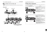
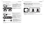
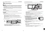
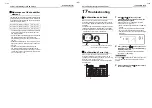
How to check
To display an error code or to confirm the operation status, the remote controller (wired remote controller and
central remote controller) is equipped with an LCD display, and the interface circuit board of the outdoor unit is
equipped with a 7 segment display. A self-diagnosis function is activated to find out the details of a problem with
the unit.
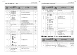
Error code list
The table below shows the error codes. See the table for details of error codes.
• To confirm the code from the remote controller, see “Wired remote controller display” in the table.
• To confirm the code from the outdoor unit, see “7 segment display on the outdoor unit” in the table.
• To confirm the code from the AI-NET central remote controller, see “AI-NET central controller display” in the
table.
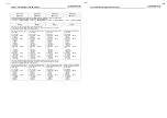
Wired
remote
controller
display
Error code
Error code name
Judging
device
7 segment display on the
outdoor unit
AI-NET
central
controller
display
Auxiliary code
E01
—
—
—
Communication error between remote controller and
indoor unit (Detected by remote controller)
Remote
controller
E02
—
—
—
Remote controller signal transmission error
Remote
controller
E03
—
—
97
Communication error between remote controller and
indoor unit (Detected by indoor unit)
Indoor
E04
—
—
04
Indoor/outdoor unit communication circuit error (Detected
by indoor unit)
Indoor
E06
E06
The number of the indoor
units received normally
04
Decrease of the number of indoor units
I/F
—
E07
—
—
Indoor/outdoor unit communication circuit error (Detected
by outdoor unit)
I/F
E08
E08
Duplicate indoor addresses
96
Indoor addresses are duplicated.
Indoor
I/F
E09
—
—
99
Header unit controllers are duplicated.
Remote
controller
E10
—
—
CF
Communication error between indoor MCUs
Indoor
E12
E12
01: Communication
between indoor unit
and outdoor unit
02: Communication
between outdoor
units
42
Automatic addressing start error
I/F
E15
E15
—
42
No indoor units during automatic addressing
I/F
E16
E16
00: Capacity over
01~:
The number of
connected units
89
Exceeding capacity (over 105%) or the number of units
I/F
E18
—
—
97·99
Communication error between header indoor unit and
follower indoor unit
Indoor
E19
E19
00: No center unit
02: 2 or more center
units
96
Error with the number of center outdoor units
I/F
E20
E20
00: Connecting outdoor
unit to another
system
01: Connecting indoor
unit to another
system
42
Connected to another system during automatic addressing
I/F
E21
E21
00: No header unit
01: Duplicated header
units
42
Error with the number of header thermal storage units
I/F
E22
E22
—
42
Decrease of the number of thermal storage units
I/F
E23
E23
—
15
Communication error between indoor and outdoor unit or
problem with the number of thermal storage units (problem
with receiving)
I/F
E25
E25
—
15
Addresses of terminal outdoor units are duplicated.
I/F
E26
E26
The number of the outdoor
units received normally
15
Decrease of the number of outdoor units
I/F
E28
E28
Detected number of outdoor
unit
d2
Follower outdoor unit error
I/F
E31
E31
01: Problem with A3-
IPDU1
02: Problem with A3-
IPDU2
03: Problem with A3-
IPDU1 and A3-
IPDU2
04: Problem with the
fan IPDU
05: Problem with A3-
IPDU and the fan
IPDU
06: Problem with A3-
IPDU2 and the fan
IPDU
07: Problem with all
IPDUs
CF
IPDU communication error
I/F
F01
—
—
0F
Indoor TCJ sensor error
Indoor
F02
—
—
0d
Indoor TC2 sensor error
Indoor
F03
—
—
93
Indoor TC1 sensor error
Indoor
F04
F04
—
19
TD1 sensor error
I/F
F05
F05
—
A1
TD2 sensor error
I/F
F06
F06
—
18
TE1 sensor error
I/F
F07
F07
—
18
TL sensor error
I/F
F08
F08
—
1b
TO sensor error
I/F
F10
F10
—
0C
Indoor TSA sensor error
Indoor
F11
F11
—
—
Indoor TF sensor error
F12
F12
—
A2
TS1 sensor error
I/F
F13
F13
01: Compressor 1 side
02: Compressor 2 side
43
TH sensor error
IPDU
F15
F15
—
zzz
Miswiring of outdoor temperature sensor (TE and TL)
I/F
F16
F16
—
—
Miswiring of outdoor pressure sensor (Pd and Ps)
I/F
F17
—
—
—
Indoor TOA sensor error
Indoor
F18
—
—
—
Indoor TRA sensor error
Indoor
F23
F23
—
43
Ps sensor error
I/F
F24
F24
—
12
Pd sensor error
I/F
F29
—
—
1C
Other indoor unit errors
Indoor
F31
F31
—
1c
Outdoor unit EEPROM error
I/F
H01
H01
01: Compressor 1 side
02: Compressor 2 side
zzz
Compressor breakdown
IPDU
H02
H02
01: Compressor 1 side
02: Compressor 2 side
1d
Compressor error (Locked)
IPDU
H03
H03
01: Compressor 1 side
02: Compressor 2 side
17
Current detection circuit error
IPDU
H04
H04
—
44
Compressor 1 case thermostat operation
I/F
Wired
remote
controller
display
Error code
Error code name
Judging
device
7 segment display on the
outdoor unit
AI-NET
central
controller
display
Auxiliary code
55-EN
56-EN


