


– 12 –
Air to Air Heat Exchanger with DX Coil Unit
Installation Manual
EN
Air to Air Heat Exchanger with DX Coil Unit
Installation Manual
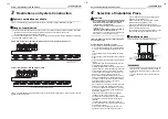
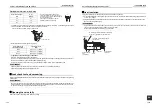
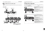
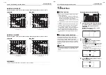
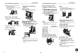
Connection diagram
1. The dotted line represents a wire procured locally, and the dashed line represents an option sold separately.
2.
represents a terminal block,
represents a connection terminal,
represents a connector on the
printed circuit board and
represents a short circuit connector.
3.
represents a protective ground.
4.
represents a printed circuit board.
5. Using a no voltage a-contact input of the external input (sold separately), the following operations are available:
Between 1 and 2: Selecting the remote controller operation (Invalid/Valid)
Between 1 and 3: Adjusting the fan speed (Low/High)
Between 1 and 5: Operation (ON/OFF)
Use a microcurrent contact (DC12V, 1mA). In addition, ON/OFF operation is possible when using a voltage of
DC12V or 24V.
6. Orange wire (High) is connected as factory default. To switch to “Extra High”, connect black wire’s connector
instead of orange.
7. The unit cannot run when the temperature of the outdoor air is below -15°C.
DC15V
DC 7V
DC12V
DC20V
2
7
7
7
7
43F11
43F12
4
6
6
2 4 2
TB1
R(L)S(N)
43F11
RY702
RY701
43F21
43F22
4
6
2 4
6
2
1
CN67
3
C
1
CN701
P01
C
43F12
8
RY705
RY704
+
+
5
3
1 3 5
CN702
43F22
8
8
43F21
8
6
5
2
1 3 4
CN760
6
1
DAM
M
1
FM1
FM2
TB2
CN040
CN82
1
CN601
CN602
1
3
1
3
634
CN34
1
3
1
3
CN706
RY708
RY710
RY709
SW701
ON
OFF
9
7
3 5
CN704
3 4 5 TB3
5
CN705
2
1
5
3 4
1
2 2
2
1
2
CN041
A B
1
A
2
1
U1 U2
3
B
2
CN106
1
2
CN104
CN105
1
2
1
TRA
t°
TOA
t°
TSA
t°
1
CN102
CN103
1
2
1
CN101
CN100
3
1
2
TCJ
TFA
t°
t°
TC2
TC1
t°
t°
6
3
2 4 5 6
M PMV
DMV1
MV1
1
TB5
2
TB4
1 2
FS1
CN61
3
2 4
1
CN81
5 6
2
1
5
4
3
Power supply for
indoor unit
220-240V~, 50Hz
220V~, 60Hz
Ground
represents the connector to switch
between Extra High and High.
Wiring between indoor
and outdoor unit
Wiring for
the remote
controller
Wired remote controller
(sold separately)
Indoor control
circuit board
MCC1615
Connector
(White)
Connector
(Black)
External output
(220-240V~, under 1A each)
*5 External input (sold separately)
No voltage a-contact input
Voltage DC (12V, 24V)
input
Operation output
White
Wh
ite
Red
Connector
(White *6)
Yellow
Connector
(Red *6)
(White)
Red
Red
Re
d
Bl
ue
Or
an
ge
Re
d
Bl
ue
Or
an
ge
Wh
ite
Ye
llo
w
Blu
e
Pu
rp
le
Re
d
1 Common
2 Remote controller operation
3 Fan speed
5 Operation
Pink
Power
supply
Bl
ac
k
Bl
ue
F01
T3.15A
250V~
Common
External damper output
Abnormal/Bypass mode
output
Red
Bl
ac
k
Bl
ue
Purple
Pink
Gray
Yellow
Blue
Blue
Yellow
Gray
Yellow
Yellow
Yellow
Bla
ck
Or
ange
Wh
ite
Wh
ite
Re
d
Yellow
Yellow
Bl
ue
Bl
ue
Bla
ck
Ora
nge
Ora
nge
Oran
ge
Black
(Red)
(White)
(Black)
(Yellow)
(Black)
(Blue)
(Brown)
(Black)
(Red)
(Green)
(Yellow)
(Blue)
(White)
(Blue)
(Blue)
(Red)
(Red)
(Blue)
(Red)
Pink
F02
T15A
250V~
Red
Red
Air to Air Heat
Exchanger with
DX Coil Unit
Code
Parts name
CN***
Connector
F01
Fuse (Printed circuit board)
F02
Fuse (Motor)
FM1
Air supplying motor
FM2
Air exhausting motor
DAM
Damper motor
TRA
TRA sensor
TOA
TOA sensor
TSA
TSA sensor
Code
Parts name
TFA
TFA sensor
TCJ, TC1, TC2 Indoor coil sensor
TB1
Terminal block (power source)
TB2
Terminal block (communication)
TB3
Terminal block (external output)
TB4
Terminal block (Humidistat)
TB5
Terminal block (Magnetic valve)
FS1
Float switch
MV1
Magnetic Valve
Code
Parts name
DMV1
Decompression magnetic valve
PMV
Pluse modulating valve
SW701
DIP switch
43F11, 43F12
Relay for air supplying motor
43F21, 43F22
Relay for air exhausting motor
RY701, RY702 Relay for air supplying motor
RY704, RY705 Relay for exhausting motor
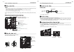
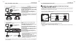
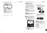
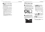
Switches and connectors on the circuit board
Remove the 4 screws to detach the cover.
* Refer to “Installation Method for Advanced System” for how to set the switch.
CN705(5P)
CN706(2P)
SW701
ON
OFF
Changeover switch for
pulse/static
SW701 (No.1)
Pulse: ON
Static: OFF
Connectors for the external input
Connect the remote ON/OFF adapter
(NRB-1HE: sold separately)
No voltage a-contact input
(Operation remote controller
valid/invalid, fan speed High/
Low)
Voltage of DC12V or 24V
(ON/OFF)
23-EN
24-EN


