DISASSEMBLY INSTRUCTIONS
B2-3
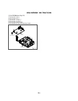
Fig. 2-6-C
Insulator (R)
Main Chassis Ass'y (Top Side)
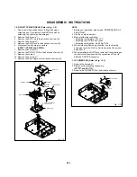
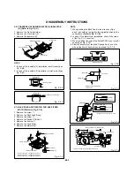
2-7:
Remove the screw
1
.
Remove the Rack Feed Ass'y.
Remove the screw
2
.
Remove the Switch PCB Ass'y.
Remove the 2 screw
3
.
Remove the Feed Motor.
Remove the Motor Gear.
1.
2.
3.
4.
5.
6.
7.
RACK FEED ASS'Y/SWITCH PCB ASS'Y/FEED
MOTOR (Refer to Fig. 2-7-A)
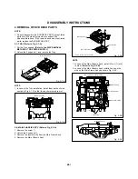
Traverse Holder
Insulator (F)
Main Chassis Ass'y
Insulator (F)
Insulator (R)
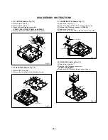
2-6:
Remove the Traverse Holder.
Remove the 2 Insulator (F).
Remove the Insulator (R).
1.
2.
3.
Fig. 2-6-A
TRAVERSE HOLDER/INSULATOR (F)/INSULATOR
(R) (Refer to Fig. 2-6-A)
NOTE
1.
2.
In case of the Insulator (F) installation, install correctly as
Fig. 2-6-B.
In case of the Insulator (R) installation, install correctly as
Fig. 2-6-C.
Fig. 2-6-B
Traverse Holder
Insulator (F)
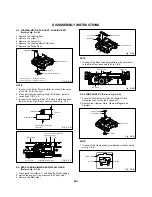
Fig. 2-7-C
6.0
±
0.2mm
Safety surface for pressing
of the insert.
Feed Motor
Motor Gear
NOTE
1.
2.
3.
4.
When pushing the Rack Feed in the direction of the
arrow, it should be restored to the original position by the
spring force. (Refer to Fig. 2-7-B)
In case of the Motor Gear installation, check if the value
of the Fig. 2-7-C is correct.
When installing the wire of the Switch PCB Ass'y, install it
correctly as Fig. 2-7-D.
After the assembly of the Main Chassis Ass'y, hook the
wire on the Main Chassis Ass'y as shown Fig. 2-7-E.
Fig. 2-7-B
Push
Rack Feed Ass'y
~ FEED MOTOR ~
BLUE (4)
ORANGE (3)
~ SPINDLE MOTOR ~
BLACK (2)
RED (1)
Fig. 2-7-D
Switch PCB Ass'y
• Install wire from (1) to (4) in order.
Main Chassis Ass'y (Bottom Side)
Check Hook
Check Hook
Fig. 2-7-E
Check Hook
Check Hook
• Loosen the wire in the direction of the arrow.
Fig. 2-7-A
• Screw Torque: 5.0
±
0.3kgf•cm (Screw
1
)
• Screw Torque: 3.0
±
0.3kgf•cm (Screw
2
)
• Screw Torque: 1.0
±
0.3kgf•cm (Screw
3
)
Main Chassis Ass'y
1
Rack Feed Ass'y
2
Switch PCB Ass'y
3
3
Motor Gear
Feed Motor


