


Installation Manual
– 28 –
EN
EN-55
EN-56
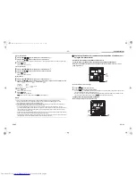
Finishing operation
1
Set the rotary switches on the interface P.C. board of the outdoor unit back: SW01 to [1], SW02 to [1] and
SW03 to [1].
<Collective test run>
Start operation
1
Set the rotary switches on the interface P.C. board of the outdoor unit as below.
When in “COOL” mode: SW01=[2], SW02=[5], SW03=[1].
When in “HEAT” mode: SW01=[2], SW02=[6], SW03=[1].
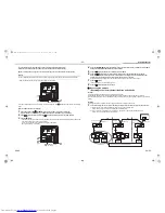
2
Push and hold SW04 for more than 2 seconds.
NOTE
• You cannot change the temperature setting during the test run.
• Errors are detected as usual.
• The unit does not perform test run for 3 minutes after turning the power on or stopping running.
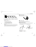
7-segment display
[A]
[U1]
[B]
[ ]
7-segment display
[A]
[C ]
[H ]
[B]
[ ]
[ ]
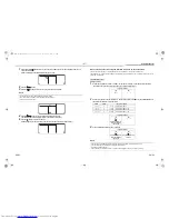
7-segment display
[A]
[C ]
[H ]
[B]
[ - C ]
[ - H ]
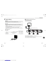
Stop operation
1
Set the rotary switches on the interface P.C. board of the outdoor unit back:
SW01 to [1], SW02 to [1] and SW03 to [1].
7-segment display
[A]
[U1]
[B]
[ ]
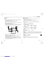
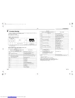
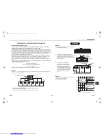
D600 D601 D602 D603 D604
SW04
SW05
SW15
SW01 SW02 SW03
Interface P.C. board
Push switch
7-segment
display [A]
Push switch
7-segment
display [B]
Rotary switches
2FAN_IM_DB04905901-00.book Page 28 Friday, October 24, 2014 3:19 PM
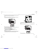
SW13
SW14
SW17
SW12
SW16
SW11
SW07
SW09
SW10
SW06
SW03
SW02
SW01
SW30
CN01
IC01
CN520
CN507
CN505
CN502
CN311
RY311
CN400
CN500
CN308
A
IC101
CN501
RY315
CN315
CN600
CN10
CN02
SW04
SW05
SW15
D600 D601 D602 D603 D604
CN800
CN802
F01
F02
CN30 CN31 CN32
Summary of Contents for MCY-MAP0401TP Series
Page 32: ......


