


– 19 –
Installation Manual
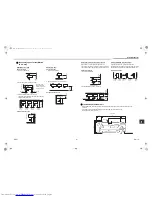
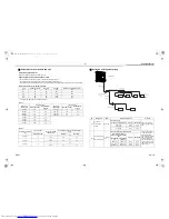
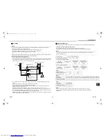
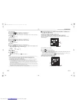
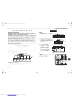
Communication wire connection
Connect the communication wires to the communication wire terminals from under the electrical control box, and fix
them with the communication cable clamps.
Screw size and tightening torque
Screw size
Tightening torque
(N•m)
Communication wire terminal
M4
1.2 to 1.4
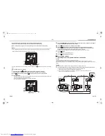
U1 U2 U3 U4
U1 U2 U3 U4
CN02
CN10
[U1, U2] and [U3, U4] not connected
Communication
terminal board
TO INDOOR
UNIT
TO CENTRAL
CONTROLLER
U1 U2 U3 U4
CN02
CN10
U1 U2 U3 U4
Communication
terminal board
TO INDOOR
UNIT
TO CENTRAL
CONTROLLER
[U1, U2] and [U3, U4] connected
U3, U4: Central control device
U1, U2: Communication wiring between Indoor / Outdoor unit
7
Address Setting
On this unit, it is required to set the addresses of the indoor units before starting air conditioning.
Set the addresses following the steps below.
CAUTION
• Be sure to complete the electric wiring before setting the addresses.
• If you turn on the outdoor unit before turning on the indoor units, the CODE No. [E19] is indicated on the 7-segment
display on the interface P.C. board of the outdoor unit until the indoor units are turned on. This is not a malfunction.
• It may take up to ten minutes (normally about five minutes) to address one refrigerant line automatically.
• Settings on the outdoor unit are required for automatic addressing. (Address setting is not started simply by turning
on the power.)
• Running the unit is not required for address setting.
• The addresses can be set manually.
Automatic addressing:
setting addresses using SW15 on the interface P.C. board on the outdoor unit
Manual addressing:
setting addresses on the wired remote controller.
* When setting an address manually, the wired remote controller must temporarily be
paired with an indoor unit one-to-one. (when the system is organized for group operation
and no Remote controller)
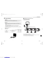
Automatic address setting
No central control (single refrigerant line):
go to Address setting procedure 1
Central control of 2 or more refrigerant lines:
go to Address setting procedure 2
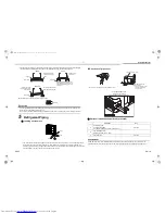
Address setting procedure 1
1
Turn on indoor units first, and then turn on outdoor units.
2
About one minute after turning the power on, confirm that the 7-segment display on the interface P.C.
board of the outdoor unit indicates
.
3
Press SW 15 to start the automatic address setting.
(It may take up to 10 minutes (normally about 5 minutes) to complete one line’s setting.)
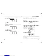
(Example)
When controlling a single refrigerant line
centrally
When controlling 2 or more refrigerant
lines centrally
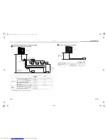
Address setting procedure
To procedure 1
To procedure 2
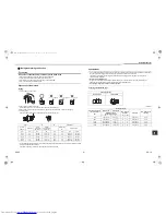
System wiring diagram
Outdoor
Outdoor
Central
controller
Central
controller
Indoor
Indoor
Indoor
Indoor
Remote
controller
Remote
controller
Remote
controller
Outdoor
Indoor
Remote
controller
Outdoor
Central
controller
Indoor
Indoor
Indoor
Remote
controller
Remote
controller
U. 1. L08 (U. 1. flash)
EN-37
EN-38
2FAN_IM_DB04905901-00.book Page 19 Friday, October 24, 2014 3:19 PM
Summary of Contents for MCY-MAP0401TP Series
Page 32: ......


