


File No. 960-140
4-36
4.13 I/O Adapter Board
Removing the I/O Adapter Board
To remove the I/O adapter board follow the steps below. (See figures 4-30 to 4-32.)
1.
Remove the
I/O adapter
from the computer. Disconnect all the external cables from
the I/O adapter.
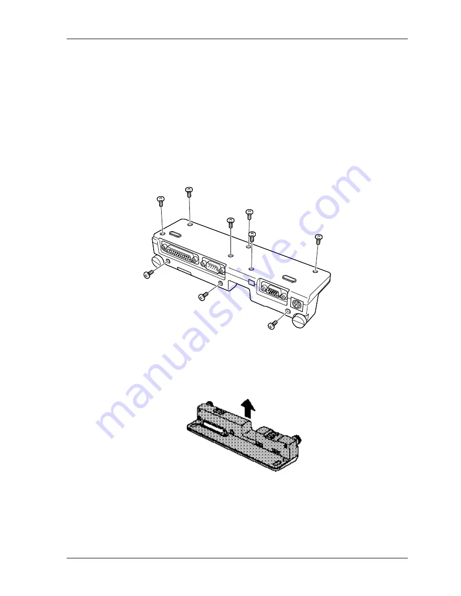
2.
Turn the I/O adapter upside down, and remove
three M2x5 silver screws
from the
back and
six M2x5 silver screws
from the bottom.
Figure 4-30 Removing nine screws
3.
Release
one latch
securing the left side,
two latches
securing the front edge and
one
latch
securing the right side and then remove the
upper cover
.
Figure 4-31 Removing the upper cover
4.
Remove
four M2x4 screws
securing the
I/O adapter board
and lift out the board.
Summary of Contents for Libretto 100CT
Page 8: ...File No 960 140 Chapter 1 Hardware Overview ...
Page 9: ...File No 960 140 1 ii ...
Page 29: ...File No 960 140 1 18 ...
Page 30: ...File No 960 140 Chapter 2 Troubleshooting Procedures ...
Page 31: ...File No 960 140 2 ii ...
Page 36: ...File No 960 140 1 3 Figure 2 1 Troubleshooting flowchart 1 2 ...
Page 72: ...File No 960 140 Chapter 3 Tests and Diagnostics ...
Page 73: ...File No 960 140 3 ii ...
Page 147: ...File No 960 140 3 72 ...
Page 148: ...File No 960 140 Chapter 4 Replacement Procedures ...
Page 149: ...File No 960 140 4 ii ...
Page 161: ...File No 960 140 4 10 3 Seat the HDD cover and fasten it with two M2x14 silver screws ...
Page 189: ...File No 960 140 4 37 Figure 4 32 Removing the I O adapter board ...
Page 191: ...File No 960 140 Appendices ...
Page 192: ...File No 960 140 App ii ...
Page 202: ...File No 960 140 A 6 ...
Page 206: ...File No 960 140 B 4 ...
Page 234: ...File No 960 140 G 2 ...
Page 236: ...File No 960 140 H 2 ...


