background image

16

Network Deployment 

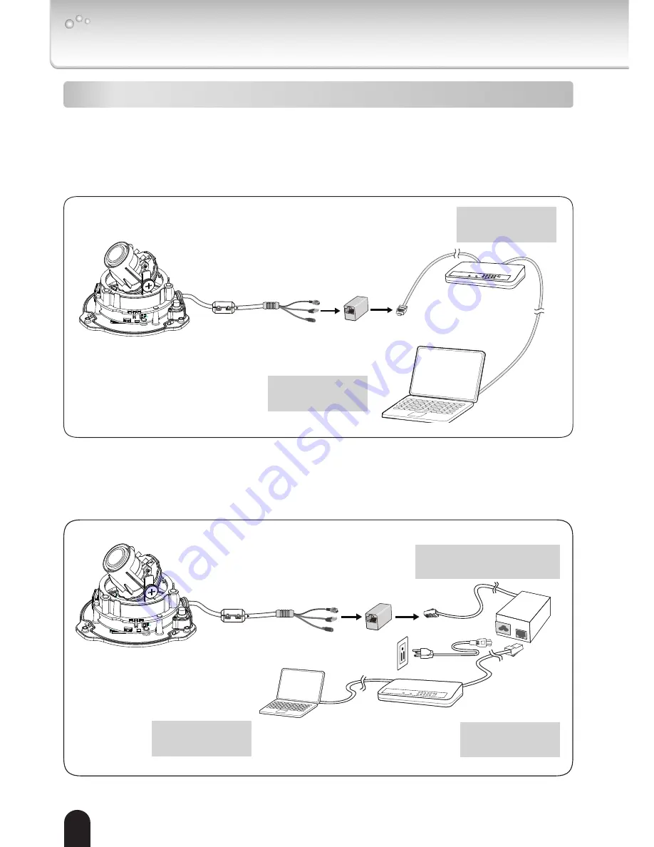
Power over Ethernet (PoE)

POWER

COLLISION

LINK

RECEIVE

PARTITION

1

2

3

4

5

POWER

COLLISION

LINK

RECEIVE

PARTITION

1

2

3

4

5

l


When using a PoE-enabled switch

The camera is PoE-compliant, allowing transmission of power and data via single LAN 

cable. See the following illustration to connect the camera to a PoE switch via LAN 

cable.

l


When using a non-PoE switch

Use a PoE power injector (not supplied) to connect between the camera and a non-PoE 

switch.

non-PoE switch

(not supplied)

PoE power injector

(not supplied)

POWER

COLLISION

LINK

RECEIVE

PARTITION

1

2

3

4

5

Client PC

(not supplied)

PoE switch

(not supplied)

Client PC

(not supplied)

Summary of Contents for IK-WR04A

Page 1: ...operations and other information The application Adobe Reader is needed to view PDF files If you do not have this application download it from the Adobe Systems Incorporated website n http www adobe com For information on our latest products and peripheral devices refer to the following Website n http www toshibasecurity com If the URL changes refer to the Toshiba website http www toshiba com ...

Page 2: ...tion If this equipment does cause harmful interference to radio or television reception which can be determined by turning the equipment off and on the user is encouraged to try to correct the interference by one or more of the following measures l Reorient or relocate the receiving antenna l Increase the separation between the equipment and receiver l Connect the equipment into an outlet on a cir...

Page 3: ...design specifications software and quick start guide contents are subject to change without prior notice Terms l The term OS is used in this manual to indicate operating systems compatible with this product Microsoft Windows XP xxx Edition Microsoft Windows Vista Business Edition Microsoft Windows 7 Professional Edition NOTE l The performance of the network camera may vary depending on the network...

Page 4: ...7 Notes on Use and Installation 8 Setting the Network Camera Environment 9 Items needed for network camera monitoring 9 Package Contents 10 Physical Description 11 Hardware Installation 12 Network Deployment 16 Assigning IP Address 18 Retrieving Images 19 Adjusting the Lens 20 Adjusting the Zoom and Focus 21 Completion 22 Trademarks 23 ...

Page 5: ...y mounting of the product should follow the manufacturer s instructions and should use a mounting accessory recommended by the manufacturer 8 Ventilation This camera should never be placed near or over a radiator or heat register If this product is placed in a built in installation verify that there is proper ventilation so that the camera temperature operates within the recommended temperature ra...

Page 6: ...this camera from the power supply and refer servicing to qualified service personnel under the following conditions a When the power supply cord or plug is damaged b If liquid has been spilled or objects have fallen into the camera c If the camera has been submerged in water d If the camera does not operate normally by following the operating instructions in the user s manual Adjust only those con...

Page 7: ...ute a risk of electric shock to persons The exclamation point within an equilateral triangle is intended to alert the user to the presence of important operating and maintenance servicing instructions in the literature accompanying the appliance WARNING TO REDUCE THE RISK OF FIRE OR ELECTRIC SHOCK DO NOT SUBMERGE THIS CAMERA IN WATER FIELD INSTALLATION MARKING WORDED THIS INSTALLATION SHOULD BE MA...

Page 8: ...the camera was submerged in water turn off the power and contact your dealer l Keep the camera installation away from video noise If cables are wired near electric lighting wires or a TV set noise may appear in images In this event relocate cables or reinstall equipment l Check the ambient temperature and humidity Avoid using the camera where the temperature is hotter or colder than the specified ...

Page 9: ...me l Recommended personal computer system requirements Windows XP Windows Vista Business or Windows 7 professional Internet Explorer Ver 8 0 CPU Intel CoreTM 2 Duo 2GHz or greater Memory 1GB RAM or greater l Connection equipment such as LAN cables and switch or router The LAN cable type differs depending on the connection method l Camera search application Installation Wizard Install this applicat...

Page 10: ...manual PDF file contained in the CD ROM for settings operations and other information The application Adobe Reader is needed to view PDF files If you do not have this application download it from the Adobe Systems Incorporated website n http www adobe com For information on our latest products and peripheral devices refer to the following Website n http www toshibasecurity com If the URL changes r...

Page 11: ...ion Lens Reset Button General I O Terminal Block Status LED Black Cover 10 100BaseT Ethernet RJ45 Plug Power Cord Socket Pin Name Digital Input GND General I O Terminal Block MicroSD SDHC Card Slot Video Out Connector 2 pins ...

Page 12: ...irst follow the instructions below to remove the dome cover Then remove the black cover as shown below Dome Cover Record the MAC address before installing the camera Tilt Adjustment Screws Lens Cover Mounting hole Mounting hole ...

Page 13: ...13 Buckle the supplied clamp filter onto the cable to prevent EMI radiation The clamp filter should be installed between the camera and cable tie as shown Cable Tie ...

Page 14: ...s 3 Drill a cable hole A Ø1 1inch Ø28mm as shown in the above picture and lead the cables through this hole 4 Align the three mounting holes of the Camera with the three plastic anchors insert the included three screws to the corresponding holes and tighten them with a driver securely Cable installation If possible lead all cables behind the camera body through a wall or ceiling If this is not pos...

Page 15: ...jury and damage l AIthough the camera and the cable on the camera s end are waterproof the cable molding at the other end is not waterproof Measures should be taken to prevent water from leaking in through the cable end molding such as the use of expanding foam sealant putties and so on Note that the cable on the camera should also be securely fastened to attain its waterproof functionality CAUTIO...

Page 16: ...mission of power and data via single LAN cable See the following illustration to connect the camera to a PoE switch via LAN cable l When using a non PoE switch Use a PoE power injector not supplied to connect between the camera and a non PoE switch non PoE switch not supplied PoE power injector not supplied POWE R COLLIS ION LINK R E C E IVE PAR TITION 1 2 3 4 5 Client PC not supplied PoE switch n...

Page 17: ...2 Connect the power cable from a power unit not supplied to the power socket 3 Connect the PC to an Ethernet switch via Ethernet cable NOTE l The recommended power supply for this camera is 6 watts minimum l When PoE is connected don t supply DC12V l Spec of DC plug is mentioned below 1 2 3 Ethernet switch not supplied Client PC not supplied Unit mm ...

Page 18: ...r window will pop up Double click on the MAC address of the appropriate device to connect to the Network Camera NOTE l If Installation Wizard does not find the camera during the search try turning off the wireless LAN of a PC l Installation Wizard can search the location of the Network Camera even though DHCP is not used on the network In this scenario assign the camera a static IP address because...

Page 19: ...19 19 For more information on camera configuration please refer to user s manual on the CD ROM 1 Access the Network Camera from the network 2 Retrieve live video through Internet Explorer Retrieving Images ...

Page 20: ... and down Upon completion tighten the screws 3 Turn the lens cover to adjust the image orientation DO NOT over rotate the lens Doing so will damage the camera lens module Using an analog monitor This camera is able to output an analog NTSC video signal from the Video Out jack Adjustment of Viewing angle is possible using a portable monitor without using a personal computer when installing Use the ...

Page 21: ...just focus range by moving the controller left and right Upon completion tighten the focus controller screw Wide Far Near Tele Focus Controller Zoom Controller NOTE l The Toshiba IK WR04A camera uses a 1M pixel sensor for displaying high resolution images After adjusting the focus and reattaching the dome cover the focus may shift due to the refractive index of the dome cover To avoid this hold th...

Page 22: ...ca gel bag attached to the camera Replace this old silica gel with a new silica gel The new silica gel is supplied in the aluminum foil bag Remove it from the foil bag before installing Please replace the silica gel with a new one if you open the dome cover after installation 3 Attach the dome cover to the camera as shown below The dome cover cannot be attatched if installed in the wrong orientati...

Page 23: ... Core are trademarks or registered trademarks of Intel Corporation or its subsidiaries in the United States and other countries l Adobe and Reader are either registered trademarks or trademarks of Adobe Systems Incorporated in the United States and or other countries l Other product names appearing in this quick start guide may be trademarks or registered trademarks of their respective holders ...

Page 24: ...TOSHIBA AMERICA INFORMATION SYSTEMS INC Surveillance IP Video Products 9740 Irvine Boulevard Irvine CA 92618 1697 Phone Number 877 855 1349 625019600G ...

Reviews: