background image

14

14

14

Notes:

l


The included screws and anchors are used to install the 

camera to a solid surface. (e.g. concrete) If installing on loose 

or thin material surfaces , use the appropriate anchors (not 

included) with the screws.

l


Generally the camera turns a built-in microphone in the 

   direction of object.

l


Install the camera securely.

l


Use Category (Cat) 5e or higher cable.

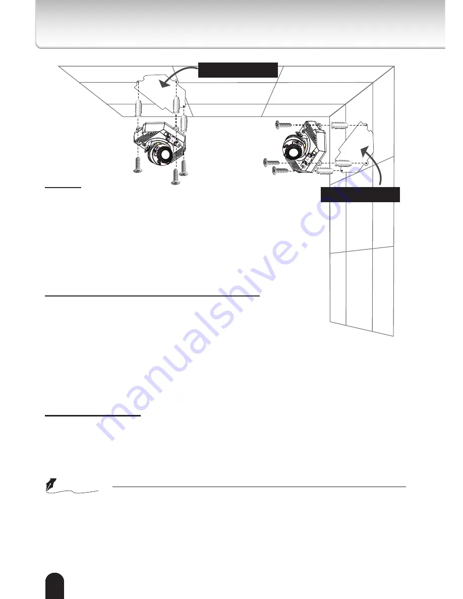
Mounting the camera to a solid surface

(1) Attach the Alignment Sticker to the surface.

(2) Drill three pilot holes (Ø0.28inch×1.57inches(D)

(Ø7mm×40mm(D))) through the three circles on the sticker.

(3) Hammer the supplied plastic anchors into the holes.

(4) Drill a hole (Ø1.0inch(Ø25mm)) behind the camera 

body on the sticker, and lead the cables through this hole.

(5) Align the three mounting holes of the Camera with the three plastic 

anchors; insert the included three screws to the corresponding holes and 

tighten them with a driver.

Cable installation

If possible, lead all cables behind the camera body through a wall or ceiling.

If this is not possible, use the knock out on the camera cover to route the 

cables through the side. 

CAUTION

l


 Installation should be done only by qualified personnel and conform to all local codes.

l


 Install this camera on a firm and solid part of the ceiling or wall.

If installed improperly or on a weak surface, the camera could fall causing injury and

damage.

Alignment sticker

Alignment sticker

Summary of Contents for IK-WD31A

Page 1: ...operations and other information The application Adobe Reader is needed to view PDF files If you do not have this application download it from the Adobe Systems Incorporated website n http www adobe com For information on our latest products and peripheral devices refer to the following Website n http www toshibasecurity com If the URL changes refer to the Toshiba website http www toshiba com ...

Page 2: ...tion If this equipment does cause harmful interference to radio or television reception which can be determined by turning the equipment off and on the user is encouraged to try to correct the interference by one or more of the following measures l Reorient or relocate the receiving antenna l Increase the separation between the equipment and receiver l Connect the equipment into an outlet on a cir...

Page 3: ...re reference The design specifications software and quick start guide contents are subject to change without prior notice Terms l The term OS is used in this manual to indicate operating systems compatible with this product Microsoft Windows Vista Business Edition Microsoft Windows 7 Professional Edition NOTE l The performance of the network camera may vary depending on the network environment ...

Page 4: ...ont 7 Notes on Use and Installation 8 Setting the Network Camera Environment 9 Items needed for network camera monitoring 9 Contents 10 Physical Description 11 Hardware Installation 13 Network Deployment 15 Assigning IP Address 17 Retrieving Images 18 Adjusting the Lens 19 Dome cover 20 Adjusting the Zoom and Focus 21 Trademarks 22 ...

Page 5: ...d tripod bracket or table recommended by the manufacturer or sold with the camera Any mounting of the product should follow the manufacturer s instructions and should use a mounting accessory recommended by the manufacturer 9 Ventilation This camera should never be placed near or over a radiator or heat register If this product is placed in a built in installation verify that there is proper venti...

Page 6: ...mera from the power supply and refer servicing to qualified service personnel under the following conditions a When the power supply cord or plug is damaged b If liquid has been spilled or objects have fallen into the camera c If the camera has been submerged in water d If the camera does not operate normally by following the operating instructions in the user s manual Adjust only those controls t...

Page 7: ...TALLATION MARKING WORDED THIS INSTALLATION SHOULD BE MADE BY A QUALIFIED SERVICE PERSON AND SHOULD CONFORM TO ALL LOCAL CODES This product is intended to be supplied by a Listed Power Adapter with LPS rated PoE 36 57V 0 35 0 15A or 12V DC 1 0A minimum The product is not likely to require connection to an Ethernet network with outside plant routing including campus environment and the installation ...

Page 8: ...allation away from video noise If cables are wired near electric lighting wires or a TV set noise may appear in images In this event relocate cables or reinstall equipment l Check the ambient temperature and humidity Avoid using the camera where the temperature is hotter or colder than the specified operating range Doing so could affect the internal parts or cause the image quality to deteriorate ...

Page 9: ...me time l Recommended personal computer system requirements Windows Vista Business or Windows 7 professional Internet Explorer Ver 8 0 CPU Intel CoreTM 2 Duo 2GHz or greater Memory 1GB RAM or greater l Connection equipment such as LAN cables and switch or router The LAN cable type differs depending on the connection method l Camera search application Installation Wizard Install this application fr...

Page 10: ...al PDF file contained in the CD ROM for settings operations and other information The application Adobe Reader is needed to view PDF files If you do not have this application download it from the Adobe Systems Incorporated website n http www adobe com For information on our latest products and peripheral devices refer to the following Website n http www toshibasecurity com If the URL changes refer...

Page 11: ...11 11 Physical Description Cover screws Knock out Internal microphone Dome cover Lens cover Tilt adjustment screws Mounting holes Clear cover ...

Page 12: ...C Card Slot Recessed Reset Button DIP switch Audio Video Out Printed AV Out 10 100BaseT Ethernet Socket MIC In Printed Audio In Microphone Video Output internal external NTSC 60Hz PAL 50Hz 1 2 General IO Terminal Block 1 GND 2 Power input 12V DC 3 Do not use 4 Do not use 5 Signal GND 6 Digital Input 7 Digital output 8 12V DC Output ...

Page 13: ...ware Installation Bottom of the Camera Dome Cover First use the supplied driver to detach the dome cover from the camera base Then follow the steps below to install the camera either to a ceiling or to a wall ...

Page 14: ...hors into the holes 4 Drill a hole Ø1 0inch Ø25mm behind the camera body on the sticker and lead the cables through this hole 5 Align the three mounting holes of the Camera with the three plastic anchors insert the included three screws to the corresponding holes and tighten them with a driver Cable installation If possible lead all cables behind the camera body through a wall or ceiling If this i...

Page 15: ...IVE PAR TITION 1 2 3 4 5 POWE R COLLIS ION LINK R E CE IVE PAR TITION 1 2 3 4 5 Power over Ethernet PoE PoE switch not supplied POWE R COLLIS ION LINK R E CE IVE PAR TITION 1 2 3 4 5 POWE R COLLIS ION LINK R E CE IVE PAR TITION 1 2 3 4 5 l When using a non PoE switch Use a PoE power injector not supplied to connect between the camera and a non PoE switch non PoE switch not supplied PoE power injec...

Page 16: ...a LAN cable 2 Connect the power cable from a power unit not supplied to the appropriate port of the general I O terminal See page 12 3 Connect the PC to an Ethernet switch via Ethernet cable Client PC not supplied 3 NOTE l Recommended power cord is twisted pair line with a minimum wire size of 18 AWG l The recommended power supply for this camera is 15 watts minimum l When PoE is connected do not ...

Page 17: ...ras on the same network 4 After searching the main installer window will pop up Double click on the MAC address of the appropriate device to connect to the Network Camera NOTE l If Installation Wizard does not find the camera during the search try turning off the wireless LAN of a PC l Installation Wizard can search the location of the Network Camera even though DHCP is not used on the network In ...

Page 18: ... 18 For more information on camera configuration please refer to user s manual on the CD ROM 1 Access the Network Camera from the network 2 Retrieve live video through Internet Explorer Retrieving Images ...

Page 19: ...ton on the camera body for 2 seconds or more The zoom lens will move to a wide position and the focus will move to the optimal position Based on the live image retrieved from the camera adjust the camera lens by performing the following To adjust the viewing angle 1 Turn the lens module left and right 2 Loosen the tilt adjustment screws on both side of the camera and then turn the lens module up a...

Page 20: ...cover to the camera l Don t touch the lens and clear cover when installing Clean the clear cover if you touch it After attaching the dome cover make sure not to cover the light sensor with dome cover 2 Secure the two dome screws with a screwdriver Make sure all parts of the camera are securely installed NOTE Light sensor Dome cover Clear cover ...

Page 21: ...e Zoom slide bar to find an optimal view of the area of interest where you want to adjust its focus Click and drag the double triangle pointer to rapidly adjust the zoom ratio Use the W or T button to adjust the zoom ratio definitely The Focus pointer moves with the Zoom pointer correspondingly 2 Select Full view from the bottom of the screen 3 Click on the Iris Open button and wait 5 seconds Lens...

Page 22: ...Core are trademarks or registered trademarks of Intel Corporation or its subsidiaries in the United States and other countries l Adobe and Reader are either registered trademarks or trademarks of Adobe Systems Incorporated in the United States and or other countries l Other product names appearing in this quick start guide may be trademarks or registered trademarks of their respective holders ...

Page 23: ...23 TOSHIBA AMERICA INFORMATION SYSTEMS INC Surveillance IP Video Products 9740 Irvine Boulevard Irvine CA 92618 1697 Phone Number 877 855 1349 625026700G ...

Reviews: