Note:
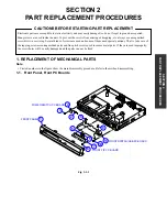
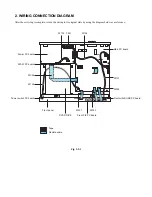
• Circled numbers in the figure show the main disassembly procedure. Refer to them when disassembling.
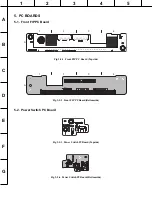
1-1. Front Panel, Front PC Boards
Fig. 2-1-1
SECTION 2
P
ART REPLACEMENT PROCEDURES
SECTION 2
PART REPLACEMENT PROCEDURES
CAUTIONS BEFORE STARTING PART REPLACEMENT
Electronic parts are susceptible to static electricity and may easily damaged, so do not forget to ground as required.
Many screws are used inside the unit. To prevent the screws from missing or dropping, etc. always use a magnetized
screwdriver in servicing. Several kinds of screws are used and some of them need special cautions. That is, take care of
the tapping screws securing molded parts and fine pitch screws used to secure metal parts. If they are used improperly,
the screw holes will be easily damaged and the parts can not be fixed.
1. REPLACEMENT OF MECHANICAL PARTS
FRONT PANEL
POWER SWITCH PC BOARD
2
5
8
9
7
10
11
6
5
3
4
1
FRONT SWITCH/USB PC BOARD
FRONT FIP PC BOARD
Summary of Contents for HD-E1KE
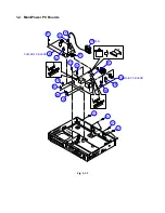
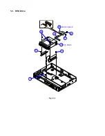
Page 12: ...1 3 DVD Drive Fig 2 1 3 DVD DRIVE ATAPI PC BOAD 7 2 1 6 3 4 5 1 1 ...
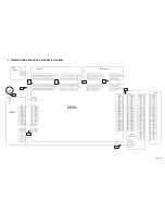
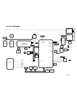
Page 18: ...Fig 3 4 1 4 CIRCUIT DIAGRAMS 4 1 Power Supply Circuit Diagram ...
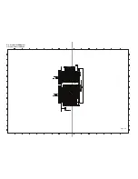
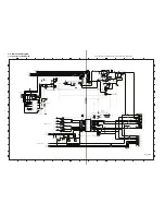
Page 19: ...4 2 Front Circuit Diagram 4 2 1 Front FIP Circuit Diagram Fig 3 4 2 ...
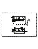
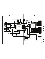
Page 20: ...Use Not use 4 2 2 Power Switch Circuit Diagram Fig 3 4 3 ...
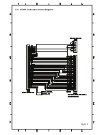
Page 22: ...Fig 3 4 5 4 3 ATAPI Conversion Circuit Diagram ...
Page 32: ...1 1 SHIBAURA 1 CHOME MINATO KU TOKYO 105 8001 JAPAN ...


