1-8-3
E7M70TR
No
Yes
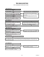
Check D1057, D1058, D1059, C1060 and their
periphery, and replace P1(AV ASSEMBLY)
if defective.
FLOW CHART NO.12
Is 5V voltage supplied to Pin(1) of IC1503?
Replace P1(AV ASSEMBLY).
No
Is 2.8V voltage supplied to Pin(1) of IC1504?
FLOW CHART NO.11
P-ON+1.8V is not outputted.
Replace P1(AV ASSEMBLY).
Check D1056, D1077, C1058 and their periphery,
and replace P1(AV ASSEMBLY) if defective.
Yes
Yes
FLOW CHART NO.14
TUNER+5V is not outputted.
ls "H" pulse outputted to Pin(53) of IC1501?
Check Q1065, D1066 and their periphery,
and replace P1(AV ASSEMBLY) if defective.
Replace P1(AV ASSEMBLY).
No
Yes
Yes
ls "L" pulse outputted to the collector of Q1056?
Replace P1(AV ASSEMBLY).
No
No
FLOW CHART NO.13
Check D1068, C1067 and their periphery,
and replace P1(AV ASSEMBLY) if defective.
TUNER+32V is not outputted.
Is 5V voltage supplied to the emitter of Q1065?
Check D1057, D1058, D1059, C1060, and their
periphery, and replace P1(AV ASSEMBLY)
if defective.
P-ON+3.3V is not outputted.
Summary of Contents for D-R560KU
Page 38: ...1 11 4 AV 2 4 Schematic Diagram E7M70SCAV2 NOTE BOARD MEANS PRINTED CIRCUIT BOARD ...
Page 39: ...1 11 5 E7M70SCAV3 AV 3 4 Schematic Diagram NOTE BOARD MEANS PRINTED CIRCUIT BOARD ...
Page 40: ...1 11 6 E7M70SCAV4 AV 4 4 Schematic Diagram NOTE BOARD MEANS PRINTED CIRCUIT BOARD ...
Page 48: ...1 11 14 DVD MAIN 6 7 Schematic Diagram E7M70SCD6 NOTE BOARD MEANS PRINTED CIRCUIT BOARD ...
Page 50: ...1 11 16 DTV MODULE 1 2 Schematic Diagram E7M70SCDTV1 NOTE BOARD MEANS PRINTED CIRCUIT BOARD ...
Page 51: ...1 11 17 DTV MODULE 2 2 Schematic Diagram E7M70SCDTV2 NOTE BOARD MEANS PRINTED CIRCUIT BOARD ...
Page 52: ...1 11 18 BE7M70F01011A BOARD AV Top View NOTE BOARD MEANS PRINTED CIRCUIT BOARD ...
Page 57: ...1 11 23 BOARD POWER SWITCH Bottom View BOARD POWER SWITCH Top View BE7M70F01011C ...
Page 62: ...1 14 3 R5NTI Push close 0 08 V 0 02 s Push Close detection Threshold level ...
Page 72: ......


