background image

2. MAJOR UNIT REPLACEMENT


EO18-33018 

(Revision Date: May 21, 2007) 

2.10 Replacing the PS Unit and Reactor 


2-21 

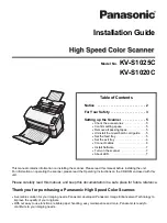
5)  Disconnect the PSU harness from CN4 on the PS unit. 


6)  Disconnect the harnesses from CN1 on the PS unit.    For the QP and CN models, disconnect the 

harness from CN2, too.


7)  Remove the two SMW-4x8 screws to detach the PS unit from the PSU base.


8)  Remove the SMW-4x8 screws to detach the reactor from the PSU base.    (QP and CN models)


B

A

B

A


CN1

PS Unit

PSU Base 

Reactor (QP and CN models) 

SMW-4x8 Screw 

CN2

SMW-4x8 Screw

Inlet Harness

Reactor Harness 

PSU Harness

CN4

PS Unit

Summary of Contents for B-852-R Series

Page 1: ...PRINTED IN JAPAN TOSHIBA Thermal Printer B 852 R SERIES Document No EO18 33018 Original Mar 2006 Revised Maintenance Manual ...

Page 2: ... Gap Sensor TR and Black Mark Sensor Upper Side 2 16 2 8 2 Feed Gap Sensor LED and Black Mark Sensor Lower Side 2 17 2 9 REPLACING THE PRINT HEAD 2 19 2 10 REPLACING THE PS UNIT AND REACTOR 2 20 3 PERIODIC MAINTENANCE PROCEDURE 3 1 4 TROUBLESHOOTING 4 1 CAUTION 1 This manual may not be copied in whole or in part without prior written permission of TOSHIBA TEC 2 The contents of this manual may be c...

Page 3: ...nd the printer from the carton Supply Holder Frame L and R Supply Holder Base Power Cord Print Head Cleaner Owner s Manual B 852 R Printer Bottom Pad Supply Holder Unit Cushion Carton Accessory Carton Supply Holder Pad A Supply Holder Pad A Supply Holder Pad B Wing Bolt Cushion Top Pad Unpacking Instruction Caution Label Instruction QQ QP model Caution Label QQ QP model ...

Page 4: ...ter on a level surface 10 Please attach the supplied Caution Label to an easily visible position on the printer QQ QP model CAUTION Do not use excessive force when closing the print head block as doing this may damage the gears 1 2 Checks 1 Check for damage or scratches on the machine 2 Confirm that none of the accessories are missing NOTE Keep the carton and pads for later transport Top Cover Tap...

Page 5: ...ach the side cover R NOTE After removing the screws unhook the side cover R from portion A by lifting and moving it toward the front of the printer 4 Remove the two B 4x6 screws PT 3x8 screw and D 4x6 screw to detach the side cover L WARNING Disconnect the power cord before replacing the parts Top Cover B 4x6 Screw B 4x6 Screw Side Cover R Portion A Side Cover R Hook D 4x6 Screw TT 3x8 Screw B 4x6...

Page 6: ...at way Lack of oil or the presence of debris or dust may cause an unexpected failure To maintain in optional operating condition periodically clean the machine and apply the proper kind of oil to each part in which lubrication is needed Although the frequency of lubrication varies according to how often the machine is used as a minimum it is necessary to lubricate before any part becomes dry It is...

Page 7: ...e 2 Remove the side cover L from the printer Refer to Section 2 1 3 Remove the three SMW 3x6 screws to detach the rear frame cover 4 Disconnect the harnesses from CN1 CN2 CN5 CN8 CN9 and CN500 on the MAIN PC board Rear Frame Cover SMW 3x6 Screw CN9 Print Head Harness Signal CN5 Media Sensor Harness CN2 Ribbon Motor Harness CN1 Print Head Harness Power CN500 Stepping Motor Harness MAIN PC Board ...

Page 8: ...emove the two SMW 4x8 screws SMW 3x6 screw and B 3x6 screw 5 Disconnect the power harness from CN8 on the MAIN PC board ass y then remove the MAIN PC board ass y from the printer SMW 3x6 Screw SMW 4x8 Screw B 3x6 Screw MAIN PC Board Ass y MAIN PC Board Ass y Power Harness CN8 ...

Page 9: ...ith a new one and reassemble in the reverse order of removal 8 After replacing the MAIN PC board perform the following operations 1 Perform a RAM clear 2 Restore the printer system setting according to the printout of the parameter settings 3 Perform a media sensor adjustment 4 Perform a test print to print to confirm that the printer works properly B 3x6 Screw SMW 3x6 MAIN PCB Support Frame MAIN ...

Page 10: ... Section 2 1 2 Remove the PT 3x8 screw to detach the operation panel ass y from the side cover L in the direction indicated by the arrow 3 Disconnect the operation panel harness from CN2 on the panel PC board 4 Disconnect the flat cable from CN3 on the panel PC board Side Cover L PT 3x8 Screw Operation Panel Ass y Operation Panel Harness CN2 CN3 Flat Cable ...

Page 11: ... washers to detach the panel PC board from the operation panel cover 6 Replace the panel PC board with a new one then reassemble in the order removal 7 Turn the power on then confirm that the LCD message is displayed properly Operation Panel Cover E Plate Key Switch Panel PC Board W 4 W 4 PT 3x6 Screw Flat Cable ...

Page 12: ...h the PCB support plate from the printer 3 Remove the two SM 4x8 screws to detach the stepping motor from the printer 4 Disconnect the harness from the stepping motor 5 Replace the stepping motor with a new one then reassemble in the reverse order of removal 6 Perform a test print to print to confirm that the printer works properly PCB Support Plate SMW 3x6 Screw Stepping Motor SM 4x8 Screw SM 4x8...

Page 13: ...JOR UNIT REPLACEMENT EO18 33018 2 5 Replacing the Stepping Motor 2 9 NOTE Apply FLOIL to the stepping motor s pulley and the motor gear when reassembling the stepping motor Motor Gear Pulley Stepping Motor ...

Page 14: ...ide cover L from the printer Refer to Section 2 1 3 Press down the head block release lever and raise the print head block 4 Remove the MAIN PC board ass y Refer to Section 2 3 2 6 1 Replacing the Head Up Sensor 1 Remove the sensor harness and the SMW 3x6 screw then remove the head up sensor from the printer 2 Push and release the hook A then release the hook B to remove the head up sensor from th...

Page 15: ...he Slit Sensor Rewind Feed 1 Remove the two SMW 3x6 screws then remove the PCB support plate from the printer 2 Remove the media sensor harness from the clamp 3 Remove the two SMW 4x6 and the two D 3x6 screws then remove the motor block from the printer 4 Remove the three SMW 3x6 screws and sensor harnesses then remove the slit sensor rewind feed from the motor block SMW 3x6 Screw PCB Support Plat...

Page 16: ...he colors of the sensor harnesses are different according to the sensor to be connected 2 Be careful not to damage the slit sensor Rewind Feed when replacing it as this may cause a malfunction 2 6 3 Replacing the Ribbon Motor Rewind Feed 1 Prior to replacing the ribbon motor print out the maintenance counter for future reference 2 Remove the SMW 2 6x6 screws to remove the ribbon motor rewind feed ...

Page 17: ...l to perform a Maintenance Counter clear 2 Secure the ribbon motors while inserting a 0 1 mm thick paper or folded backing paper between the ribbon motor pulley and the idler gear to adjust the backlash After the ribbon motors is secured remove the paper 4 Perform a test print to print to confirm that the printer works properly Ribbon Motor Pulley Rewind Ribbon Motor Pulley Feed Idler Gear Idler G...

Page 18: ...ing down the head block release lever 3 While pulling the top part of the platen holders L and R to the center of the printer move them to the front of the printer to remove 4 Push the platen and strip plate to the left side and then move them to the front side to remove 5 Remove the shaft holder from the platen NOTE Be careful not to damage the shaft holder when removing it 1 2 Top Cover Platen H...

Page 19: ...2 15 6 Replace the platen with a new one then reassemble in the reverse order of removal NOTE When reassembling confirm the orientation of the shaft holder See the picture below 7 Perform a test print to confirm that the printer works properly Shaft Holder Platen ...

Page 20: ...1 When reassembling the sensor case cap fit the hooks of the sensor case into portion A of the sensor case cap 2 When reassembling the sensors align the pins on the sensor case with the holes of the sensors 3 Connect the harness including the green wire to the black mark sensor Upper side 4 Pass the media sensor harness between the harness guides 5 Since connectors of the sensors are small be care...

Page 21: ...itner 5 Turn over the sensor block 6 Pull up the two tabs of the sensor case cap to remove it from the sensor case 7 Remove the feed gap sensor LED and black mark sensor lower side from the sensor case and disconnect the media sensor harness from each sensor 8 Replace the sensor with a new one then reassemble in the reverse order of removal A A SMW 4x8 Screw Front Cover Spring Spring To CN15 on th...

Page 22: ... the pins on the sensor case with the holes of the sensors 3 Connect the harness including the green wire to the black mark sensor lower side 4 Pass the media sensor harness between the harness guides 5 Since connectors of the sensors are small be careful not to break their pins Black Mark Sensor Lower side Green Sensor Case Sensor Guide Media Sensor Harness Feed Gap Sensor LED Number of pins 2 Pi...

Page 23: ...fitting its holes into the spring and print head fixing pin 2 After replacing the print head refer to Section 6 8 to perform a Maintenance Counter Clear CAUTION 1 Never touch the print head element when handling the print head 2 Never touch the connector pins to avoid a breakdown of the print head by static electricity 3 Never remove the screws which secure the print head to the bracket Doing so m...

Page 24: ...k 3 Remove the platen 4 Remove the four SMW 4x8 screws to remove the power supply block from the printer block WARNING 1 Hazardous electrical parts Before disassembling the unit unplug the power cord from the mains 2 As the printer block and PS unit are heavy be careful not to pinch your fingers or drop it on your feet 3 The PS unit should be replaced as a unit Never disassemble the PS unit Doing ...

Page 25: ...es from CN1 on the PS unit For the QP and CN models disconnect the harness from CN2 too 7 Remove the two SMW 4x8 screws to detach the PS unit from the PSU base 8 Remove the SMW 4x8 screws to detach the reactor from the PSU base QP and CN models B A B A CN1 PS Unit PSU Base Reactor QP and CN models SMW 4x8 Screw CN2 SMW 4x8 Screw Inlet Harness Reactor Harness PSU Harness CN4 PS Unit ...

Page 26: ... then reassemble in the reverse order of removal WARNING Pass the reactor harness and inlet harness through the cut in the PS unit frame Care must be taken not to pinch the harnesses in the frame Failure to do this may break the harnesses causing a fire or electric shock Reactor Harness PS Unit PSU Base Inlet Inlet Harness Cut ...

Page 27: ...o the following general maintenance procedure and perform periodic servicing NOTE Before starting the periodic maintenance be sure to read carefully and understand the Service Manuals especially warnings cautions and adjustment 1 Ask an operator or a manager about any machine trouble 2 Check the run distance on the maintenance counter 3 Unplug the power cord and then open the top cover and the hea...

Page 28: ...nt head elements with the TOSHIBA TEC approved print head cleaner Please instruct your customers to clean them daily 4 Remove any paper dust and glue of the label Wipe off moving range of the media sensor Print Head Cleaner Print Head Element Moving range of the Media Sensor Print Head Media Path ...

Page 29: ...aintained cutter is used with TOSHIBA TEC approved supplies by the proper method described in the manuals 2 The above values differ depending on the thickness and substances of the media to be used When using the cutter to cut the labels be sure to cut the backing paper Failure to do this may cause the glue to stick to the cutter and shorten the cutter life 8 Confirm each part adjustment Make any ...

Page 30: ...3 PERIODIC MAINTENANCE PROCEDURE EO18 33018 3 PERIODIC MAINTENANCE PROCEDURE 3 4 11 Clean the outside of the printer 12 Fill out a report form Hand it to the manager and obtain a signature ...

Page 31: ...se the media approved by TOSHIBA TEC Clean the print head Close the print head block completely Printer does not print 1 Print head failure 2 Connection of the print head connector is incomplete a bad contact or broken elements 3 Failure in rewinding feeding of the ribbon 4 Failure of the MAIN PC board 5 Failure of the software 6 Failure of the printer cable Replace the print head Connect the harn...

Page 32: ...motor Set the media properly Use the media approved by TOSHIBA TEC Re adjust the sensor Set the threshold correctly Replace the feed gap sensor or black mark sensor Install the cutter module properly Replace the stepping motor or MAIN PC board Communication error 1 Failure of the communication cable 2 Failure of the RS 232C connector 3 Failure of the communication connector 4 Failure of the PC or ...

Reviews: