


- 6 -
WARNING :
BEFORE SERVICING THIS CHASSIS, READ THE “X-RAY RADIATION PRECAUTION”, “SAFETY PRE-
CAUTION” AND “PRODUCT SAFETY NOTICE” ON PAGE 3 OF THIS MANUAL.
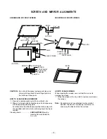
PICTURE TUBE COMPONENTS ADJUSTMENT
DESCRIPTION OF NECK COMPONENTS
���
Deflection yoke and convergence yoke
The position on the neck is required most front
(CRT funnel side) and the screw is fastened after
rotating yoke adjusting picture tilt.
���
Centering magnet
After adjusting picture tilt, picture position is finally
fixed by this magnet.
In order to get maximum margin of user conver-
gence control for center of screen, this magnet
have to be used for center convergence adjust-
ment.
PREPARATION
Operate the receiver for at least 5 minutes.
���
���
Summary of Contents for 51HX84
Page 1: ...SERVICE MANUAL Projection Television 51HX84 57HX84 N4PS Chassis FILE NO 020 200410 ...
Page 8: ... 8 LOCATION OF SCREEN AND FOCUS VR S FOCUS COVER Speaker grille G B R SCREEN ...
Page 35: ...SCAN CONVERTER MODUL MHSU11 PD1738 U001 BOTTOM FOIL SIDE 36 37 ...
Page 36: ...SCAN CONVERTER MODUL MHSU11 PD1738 U001 TOP COMPONENT SIDE 38 39 ...
Page 44: ... 51 52 CIRCUIT BLOCK DIAGRAM ...
Page 46: ...TOSHIBA CORPORATION 1 1 SHIBAURA 1 CHOME MINATO KU TOKYO 105 8001 JAPAN ...