background image

7

DLP Inst (E/F) Web 213:276

Connecting your TV

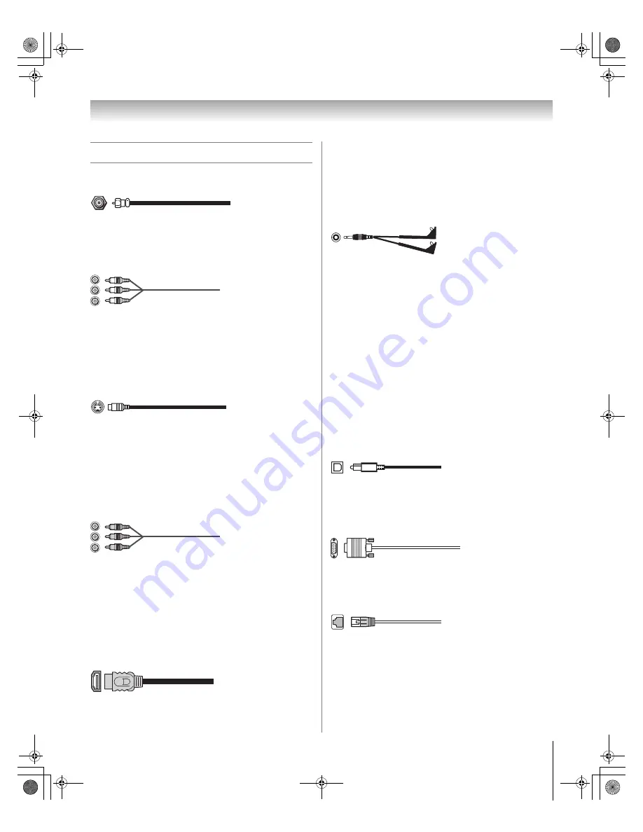
Overview of cable types

Coaxial (F-type) cable

Coaxial (F-type) cable is used for connecting your antenna, 
cable TV service, and/or cable converter box to the 

ANT 1


and/or 

ANT 2

 RF inputs on your TV.

Standard A/V cables (red/white/yellow)

Standard A/V cables (composite video) usually come in sets of 
three, and are for use with video devices with analog audio and 
composite video output. These cables (and the related inputs 
on your TV) are typically color-coded according to use: yellow 
for video, red for stereo right audio, and white for stereo left 
(or mono) audio.

S-video cable

S-video cable is for use with video devices with S-video 
output. Separate audio cables are required for a complete 
connection.

Note: 

An S-video cable provides better picture performance 

than a composite video cable. If you connect an S-video cable, 
be sure to disconnect the standard (composite) video cable or 
the picture performance will be unacceptable.

Component video cables (red/green/blue)

Component video cables come in sets of three and are for use 
with video devices with component video output. 
(ColorStream

®

 is Toshiba’s brand of component video.) These 

cables are typically color-coded red, green, and blue. Separate 
audio cables are required for a complete connection.

Note: 

Component video cables provide better picture 

performance than a standard (composite) video or S-video 
cable.

HDMI™ cable

HDMI (High-Definition Multimedia Interface) cable is for use 
with devices with an HDMI output. An HDMI cable delivers 
digital audio and video in its native format. This cable carries 

both video and audio information; therefore, separate audio 
cables are not required for a complete HDMI device 
connection (

-

 page 13).

Note: 

HDMI cable provides better picture performance than a 

standard (composite) video or S-video cable.

Dual-wand IR blaster/G-LINK™ cable

Dual-wand IR blaster/G-LINK™ cable is for use with video 
devices with IR (infrared) remote control. This cable is for 
connection to the 

G-LINK™

 terminal (

-

 page 17) to enable 

TV Guide On Screen™ recording features (

-


TV Guide 

On Screen™ Interactive Program Guide

). This cable also can 

be used with the TV’s IR pass-through feature (

-

 page 14).

Notes: 

This applies only to TV models that have the TV Guide 
On Screen™ feature. To verify whether your TV model has 
this feature, see the table on page 5.

The IR blaster/G-LINK™ cable included with your TV have 
specific characteristics that allow them to work properly with 
this TV’s 

IR OUT

 and 

G-LINK™

 ports. Never use other 

aftermarket IR blaster or G-LINK™ cables with this TV. Other 
cables may not function properly and can cause damage. 
THIS TYPE OF DAMAGE IS NOT COVERED BY YOUR 
TOSHIBA WARRANTY.

Optical audio cable

Optical audio cable is for connecting receivers with Dolby 
Digital or PCM (pulse-code modulation) optical audio input to 
the TV’s 

DIGITAL AUDIO OUT

 terminal (

-

 page 16).

Analog RGB (15-pin) computer cable

Analog RGB (15-pin) computer cable is for connecting a PC to 
the TV’s 

PC IN

 terminal (

-

 page 18).

Ethernet (RJ-45) cable

Ethernet (RJ-45) cable is used to connect the TV to your home 
network (

-

 page 19 and the 

Operating Guide

).

DLP_Inst.book  Page 7  Wednesday, February 22, 2006  6:18 PM

Summary of Contents for 50HMX96 - 50" Rear Projection TV

Page 1: ...O D U C T S L L C 50HM66 56HM66 50HMX96 56HMX96 62HM196 72HM196 62MX196 72MX196 62MZ196 72MZ196 YC N VX1A00004000 Integrated High Definition DLP Projection Television 2006 TOSHIBA CORPORATION All Rights Reserved DLP_Inst book Page 1 Wednesday February 22 2006 6 18 PM ...

Page 2: ...each for a Remember that children can become excited while watching a program and can potentially push or pull a TV over a Share our safety message about this hidden hazard of the home with your family and friends Thank you Safety Precautions WARNING TO REDUCE THE RISK OF FIRE OR ELECTRIC SHOCK DO NOT EXPOSE THIS APPLIANCE TO RAIN OR MOISTURE The lightning flash with arrowhead symbol within an equ...

Page 3: ...sk of electric shock do not use the polarized plug with an extension cord receptacle or other outlet unless the blades can be inserted completely to prevent blade exposure To prevent electric shock match wide blade of plug to wide slot fully insert 16 WARNING This product contains a lamp to project the picture and requires special safety precautions See the Operating Guide for instructions on lamp...

Page 4: ...s become frequent or continuous unplug the power cord and contact a Toshiba Authorized Service Center 35 Special care for DLP Digital Light Processing units The lamp unit in this product has a limited service life The length of service life varies depending on product use or user settings If you use the lamp beyond its service life you may notice a reduction in the colors and or brightness of the ...

Page 5: ...n feature therefore the TV Guide On Screen Interactive Program Guide is not provided in the accessory pack Screen captures provided in this Installation Guide may not match the screens that you see on your TV Please refer to your Operating Guide Terminal Specifications for DLP Projection Televisions This Installation Guide includes installation instructions for several television models Please con...

Page 6: ...olorStream component video a VCR and a satellite receiver 11 Connecting a VCR with S video and a cable box 12 Connecting an HDMI or DVI device to the HDMI input 13 Connecting a device to the IR OUT infrared terminal using the IR blaster cable for IR pass through device control 14 Connecting an IR receiver repeater control system to the IR IN infrared terminal 15 Connecting a camcorder 15 Connnecti...

Page 7: ... with an HDMI output An HDMI cable delivers digital audio and video in its native format This cable carries both video and audio information therefore separate audio cables are not required for a complete HDMI device connection page 13 Note HDMI cable provides better picture performance than a standard composite video or S video cable Dual wand IR blaster G LINK cable Dual wand IR blaster G LINK c...

Page 8: ...he digital cable through a VCR first and or to ANT 2 the TV may not receive the signals correctly Always use the EJECT button to remove the CableCARD Removing the CableCARD without pressing EJECT can damage the CableCARD and or TV Such damage is NOT covered under your Toshiba warranty Never insert any object or card other than a CableCARD including without limitation a PCMCIA card into the CableCA...

Page 9: ...ng Guide Chapter 2 In the United States TV GUIDE and other related marks are registered marks of Gemstar TV Guide International Inc and or one of its affiliates In Canada TV GUIDE is a registered mark of Transcontinental Inc and is used under license by Gemstar TV Guide International Inc IN from ANT VIDEO AUDIO OUT to TV L R R L IN OUT IN OUT OUT IN CH 3 CH 4 TV Stereo VCR From Cable TV or antenna...

Page 10: ...el the Cable box output is set to Use the Cable box controls to change channels To view the VCR Turn ON the VCR Select the VIDEO 1 video input source on the TV To select the video input source press INPUT on the remote control Operating Guide To program the TV remote control to operate other devices see the Operating Guide Chapter 2 IN from ANT VIDEO AUDIO OUT to TV L R R L IN OUT IN IN OUT OUT OU...

Page 11: ...er has HDMI video see page 13 Note The VIDEO AUDIO OUT terminals output signals from the ANT 1 ANT 2 VIDEO 1 and VIDEO 2 terminals when the appropriate input mode is selected To select the video input source press INPUT on the remote control Operating Guide To program the TV remote control to operate other devices see the Operating Guide Chapter 2 To view antenna or Cable channels Select the ANT 1...

Page 12: ...n the VCR and Cable box connection To use the TV Guide On Screen recording features if applicable to your TV model 1 Connect the G LINK cable according to the instructions page 17 2 Make sure the VCR is connected to the VIDEO AUDIO OUT terminals on the TV see illustration 3 Set the VCR to the appropriate line input refer to your VCR owner s manual for details and then turn OFF the VCR 4 See the TV...

Page 13: ...ector per DVI device For proper operation the length of an HDMI to DVI adapter cable should not exceed 9 8 ft 3m The recommended length is 6 6 ft 2m one pair of standard analog audio cables per DVI device An HDMI to DVI adapter cable transfers video only Separate analog audio cables are required see illustration See Setting the HDMI audio mode in the Operating Guide Note To ensure that the HDMI or...

Page 14: ...ntrol the device s Point either the device s remote control or the TV remote control that you previously programmed to operate the device Operating Guide Chapter 2 toward the front of the TV and press the button for the desired function The signal passes from the remote control through the TV to the device via the IR blaster cable Notes If you use the device s remote control to operate the device ...

Page 15: ... performance if your camcorder has S video use an S video cable plus the audio cables instead of the standard video cable Do not connect both types of video cable to VIDEO 2 at the same time or the picture performance will be unacceptable To view the camcorder video Select the VIDEO 2 video input source on the TV To select the video input source press INPUT on the remote control Operating Guide To...

Page 16: ...rly creating a high noise level that may damage speakers or headphones THIS DAMAGE IS NOT COVERED BY YOUR WARRANTY The DIGITAL AUDIO OUT terminal outputs signals only when receiving digital broadcasts with the TV in single window mode The DIGITAL AUDIO OUT terminal may not output some digital audio sources because of copy restrictions Manufactured under license from Dolby Laboratories Dolby and th...

Page 17: ...o the G LINK terminal 1 Locate the infrared sensor on the front of your VCR or Cable box The sensor is marked on some devices 2 Align one of the G LINK IR blaster cable s wands about 1 inch away from the infrared sensor on the front of the VCR and attach it using double sided mounting tape If you have a Cable box attach the other wand in a similar manner See illustration Note If you do not have a ...

Page 18: ...Guide Notes Some PC models cannot be connected to this TV An adapter is not needed for computers with a DOS V compatible mini D sub15 pin terminal Depending on the DVD s title and the specifications of the PC on which you are playing the DVD Video some scenes may be skipped or you may not be able to pause during multi angle scenes Only models that include a PC IN VGA port are suitable for connecti...

Page 19: ...mpatible only with Microsoft Windows 2000 and the Home or Professional version of Microsoft Windows XP Service Pack 1 and Service Pack 2 See Operating Guide for details The TV s home network connection allows access to e mail scheduling and file sharing only You will NOT be able to use the TV to access the Internet If you use an Ethernet crossover cable to connect your PC directly to the TV you wi...

Page 20: ...em DSL or cable 2 1 Your router switch may be part of your DSL or cable modem Your switch may be separate from your router For assistance contact your ISP or an IT professional 2 Coaxial or telephone cable depending on your modem type 3 Standard Ethernet RJ 45 cable 4 Do NOT connect a phone jack directly to the TV s RJ 45 Ethernet port 3 2 3 4 3 1 TV back panel Modem DSL or cable Router switch PC ...

Page 21: ...tal Audio Out 16 Dolby Digital 16 DSL modem 20 DVD player connection 11 DVI connection 13 E Ethernet RJ 45 cable 7 G G LINK connection 17 H HDMI cable 7 HDMI connection 13 Home network connection 19 I Installation care and service 3 IR blaster 14 O Optical audio cable 7 P PC connection 18 R RJ 45 THINC connection 19 Router 20 S Safety 2 Service 4 S video cable 7 V VCR connection 9 10 11 12 Video c...

Page 22: ...DLP Inst E F Web 213 276 22 Notes DLP_Inst book Page 22 Wednesday February 22 2006 6 18 PM ...

Page 23: ...DLP Inst E F Web 213 276 23 Notes DLP_Inst book Page 23 Wednesday February 22 2006 6 18 PM ...

Page 24: ...ght Processing DLP and the DLP medallion are trademarks of Texas Instruments MANUFACTURED BY HEAD OFFICE 191 McNABB STREET MARKHAM ONTARIO L3R 8H2 CANADA TEL 905 470 5400 SERVICE CENTERS TORONTO 191 McNABB STREET MARKHAM ONTARIO L3R 8H2 CANADA TEL 905 470 5400 MONTREAL 18050 TRANS CANADA KIRKLAND QUEBEC H9J 4A1 CANADA TEL 514 390 7766 VANCOUVER 13551 COMMERCE PARKWAY SUITE 110 RICHMOND B C V6V 2L1...

Reviews: