background image


25


Notices

  For N on-wir eless  Pr oduct  

34


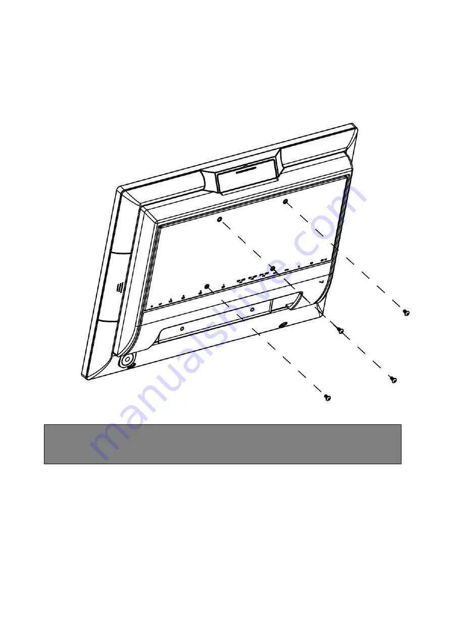
3.5. Installing The VESA 

1.  Attach the VESA wall-mounting plate to the back of the POS PC, using a Phillips 

M4 screwdriver to tighten the four screws. It should take about 5

–10 turns of the 

screwdriver to secure the screws. 


CAUTION: The VESA wall-mounting plate is not accessory. The illustration is for 
user reference only. 


Summary of Contents for 4818-T10

Page 1: ...Toshiba Global Commerce Solutions User s Manual 4818 T10 ...

Page 2: ...2 Cash Drawer 19 3 Preparing Your POS PC For Wall mounting 21 3 1 What You Need 21 3 2 Safety Information 21 3 3 Before Removing The Stand 21 3 4 Removing The POS PC Stand 22 3 5 Installing The VESA 25 4 Reinstalling The POS PC Stand 26 4 1 What You Need 26 4 2 Safety Information 26 4 3 Before Reinstalling The Stand 26 4 4 Reinstalling The POS PC Stand 27 5 Specification 31 5 1 Basic Specification...

Page 3: ...rschriften Ennen kuin asennat tämän tuotteen lue turvaohjeet kohdasta Safety Information Avant d installer ce produit lisez les consignes de sécurité Vor der Installation dieses Produkts die Sicherheitshinweise lesen Prima di installare questo prodotto leggere le Informazioni sulla Sicurezza Les sikkerhetsinformasjonen Safety Information før du installerer dette produktet Antes de instalar este pr...

Page 4: ...4 1 1 1 Hardware Setup 1 1 Packing Contents 1 Device X 1 2 RJ50 to DB9 COM port adapter cable X 2 3 Power Adapter X 1 4 Manual DVD X 1 ...

Page 5: ... Quick Tour Front View LED Indicator The Power indicator will glow green when power is on The Storage indicator will blink green when the SATA storage is accessed The LAN indicator will blink green when transferring data through the LAN Back View ...

Page 6: ...DB9 convert cable D 2 x RS232 by DB 9 COM2 COM1 E 2 x 12V PoweredUSB F 1 x 24V PoweredUSB G 4 x USB3 0 H 1 x Gigabit Ethernet RJ 45 I 1 x Cash Drawer RJ12 J 1 x 24VDC input 4 pins jack 1 3 Basic Peripherals Installation All cables and wires from peripherals to the Point Of Sale POS device are recommended to connected as the direction as shown below ...

Page 7: ...POS and then connect to the mains power supply Connect the 4 pin output jack of the adapter to the DC 24V jack on the back panel of the device USB Mouse USB Keyboard and USB Optical Disk Driver ODD Connect your USB Mouse USB Keyboard and USB Optical Disk Driver ODD to USB ports on the back panel of the device ...

Page 8: ...e Connect one end of RJ 45 LAN cable to the LAN port on the back panel of the device and the other end to your internet device Cash Drawer Connect one end of RJ 12 cable to the Cash Drawer port on the back panel of the device and the other end to your cash drawer ...

Page 9: ...e of the custom monitor 2nd display and then connect to the device as shown below NOTE 2nd display cable need remove the connector cover first 3 Mount the customer display to the device and tighten the two PHILLIPS M3 screws as shown below 4 Please install 2nd display USB driver after device installation Please visit product web site and get driver http service ebn com tw tgcs ...

Page 10: ...et PC Settings on the Windows Control Panel and click the Settings button Following the display instruction manually touching the touch screen twice then the main touch will operate correctly on the main display Customer VFD 1 Remove the top peripheral mounting hole cover from the device and pull out the connector from the device ...

Page 11: ...t to the device as shown below NOTE VFD cable need remove the connector cover first 3 Mount the customer display to the device and tighten the two PHILLIPS M3 screws as shown below 4 Please install driver utility after device installation Please visit product web site and get driver http service ebn com tw tgcs ...

Page 12: ...12 MSR iButton NOTE MSR iButton only can be installed on the right side 1 Remove the right side peripheral cover from the system 2 Install the adaptor ...

Page 13: ... iButton cable need remove the connector cover 4 Combine the MSR iButton into side peripheral door of system tighten the two PHILLIPS M3 screws to fix the MSR assembly as shown below 5 Please install driver utility after device installation Please visit product web site and get driver http service ebn com tw tgcs ...

Page 14: ...ghtly slide down 4 Hold system board box with one hand and slightly uplift the pulling tab with another hand 5 Loosen screw with 1 Philips screw driver and remove the M 2 from the slot 6 Align and insert the new M 2 storage in the slot and push end down into place and tighten the screw 7 Close the system board box carefully then place system board box into POS terminal system correctly ...

Page 15: ...m board box open 2 Release the two ejectors on the slot by pushing them and remove the memory module from the slot 3 Align and insert the new memory module in the slot and push both ends down until the ejectors snap into place 4 Close the system board box carefully then place system board box into POS terminal system correctly ...

Page 16: ...freely from 25 to 90 Hold both sides of the LCD frame and slowly push the display upward downward to your best angle 1 7 Turn On The Device 1 Make sure all peripherals are connected properly 2 Press and hold the power switch until the power indicator on the front panel glow green 25 90 ...

Page 17: ...cal information about all I O ports as followings 2 1 Serial Port COM1 COM2 by direct DB9 connector COM3 COM4 by RJ50 connector with convert to DB9 cable DB9 pin9 with NA 5V 12V by BIOS selection RS 232 PIN Description PIN Description 1 DCD 6 DSR 2 RXD 7 RTS 3 TXD 8 CTS 4 DTR 9 NA 5V 12V 5 GND ...

Page 18: ...18 ...

Page 19: ...it0 pin output control Cash Drawer DOUT bit1 pin output control Reserved Cash Drawer DIN bit0 pin input status Reserved bit 7 6 5 4 3 2 1 0 Attribute Reserved Read Reserved Write Reserved BIT7 Reserved BIT6 Cash Drawer DIN bit0 pin input status 1 The Cash Drawer opened 0 The Cash Drawer closed or no Cash Drawer BIT5 Reserved BIT4 Reserved BIT3 Cash Drawer DOUT bit1 pin output control 1 Opening the...

Page 20: ...ning O 48C 00 Allow to close SettheI Oaddress48Chbit2 1foropeningCashDrawerby DOUTbit0 pin control Set the I O address 48Ch bit2 0forallowclose Cash Drawer Command Cash Drawer I 48C Check status The I Oaddress48Chbit6 1meanthe Cash Drawerisopenedornotexist TheI Oaddress48Chbit6 0meantheCashDrawerisclosed ...

Page 21: ...fore removing the stand Failure to do so before you perform any procedures can result in personal injury or equipment damage WARNING Avoid touching sharp edges inside the POS PC 3 3 Before Removing The Stand To avoid injury and equipment damage when opening the POS PC always complete the following steps in order 1 Remove any media and external devices such as any CD DVD memory cards USB devices or...

Page 22: ...connect the power adapter from of the POS PC 4 Disconnect all other attached cables from the back of the POS PC 3 4 Removing The POS PC Stand 1 Remove the cable cover from the POS PC 2 Release 2 thumb screws of System board Box then slightly slide down ...

Page 23: ...23 Notices For N on wir eless Pr oduct 34 3 Use a Phillips M3 screwdriver to remove the five screws on the bracket plate 4 Lift the stand away from the touch monitor ...

Page 24: ...em board Box using a Phillips screwdriver to tighten the two screws 6 Align the cable cover to the System board Box and snap it back into place Make sure that there are no gaps between the System board Box and the cable cover ...

Page 25: ... VESA wall mounting plate to the back of the POS PC using a Phillips M4 screwdriver to tighten the four screws It should take about 5 10 turns of the screwdriver to secure the screws CAUTION The VESA wall mounting plate is not accessory The illustration is for user reference only ...

Page 26: ...ilure to do so before you perform any procedures can result in personal injury or equipment damage WARNING Avoid touching sharp edges inside the POS PC 4 3 Before Reinstalling The Stand To avoid injury and equipment damage when opening the POS PC always complete the following steps in order 1 Remove any media and external devices such as any CD DVD memory cards USB devices or external hard disk dr...

Page 27: ...ely shut down disconnect the power adapter from of the POS PC 4 Disconnect all other attached cables from the back of the POS PC 4 4 Reinstalling The POS PC Stand 1 Use a Phillips M4 screwdriver remove wall mounting back four screws 2 Remove the cable cover from the POS PC ...

Page 28: ...28 3 Release 2 thumb screws of System board Box then slightly slide down 4 Put back the stand away from the touch monitor ...

Page 29: ...r oduct 34 5 using a Phillips M3 screwdriver to tighten the five screws It should take about 5 10 turns of the screwdriver to secure the screws 6 Place back the System board Box using a Phillips screwdriver to tighten the two screws ...

Page 30: ...30 7 Align the cable cover to the System board Box and snap it back into place Make sure that there are no gaps between the System board Box and the stand cover ...

Page 31: ...nel type Bezel Free Tilting Angle 25 90 Storage Device Interface SATA 3 0 Gb S x 1 SSD m 2 support B M type 2280 slot x 1 I O Ports Audio 3 5mm 4 conductor Combo CTIA Audio jack x 1 Line out and Mic in Video Mini DisplayPort x 1 Serial COM1 COM2 DB9 RS232 pin9 with NA 5V 12V by BIOS selection COM3 COM4 RJ50 with convert to DB9 cable DB9 pin9 with NA 5V 12V by BIOS selection USB 12V PoweredUSB x 2 ...

Page 32: ... panel Panel backlight type LED with 30K hours of life Brightness 350 nits typ w o touch Resolution 1024 x 600 Interface USB Dimension W x D x H 26 2 x 4 2 x 16 9 cm 10 4 x 1 7 x 6 6 inch Net Weight Gross Weight 1 2 kg 2 7 lb Color Black Customer VFD 20 Characters x 2 lines VFD dot display to be installed onto the POS terminal MSR ISO Track 1 2 3 type magnetic card reader kit Magnetic stripe card ...

Page 33: ...33 Notices For N on wir eless Pr oduct 34 6 6 Dimension mm ...

Page 34: ...hese patents You can send license inquiries in writing to Toshiba Global Commerce Solutions Attn General Counsel 3901 South Miami Blvd Durham NC 27703 United States of America The following paragraph does not apply to the United Kingdom or any other country where such provisions are inconsistent with local law TOSHIBA GLOBAL COMMERCE SOLUTIONS PROVIDES THIS PUBLICATION AS IS WITHOUT WARRANTY OF AN...

Page 35: ...mful interference to radio communications Operation of this equipment in a residential area is likely to cause harmful interference in which case the user will be required to correct the interference at his own expense Properly shielded and grounded cables and connectors must be used in order to meet FCC emission limits Toshiba Global Commerce Solutions is not responsible for any radio or televisi...

Page 36: ...ndbüchern beschrieben zu installieren und zu betreiben Des Weiteren dürfen auch nur von der Toshiba Global Commerce Solutions empfohlene Kabel angeschlossen werden Toshiba Global Commerce Solutions übernimmt keine Verantwortung für die Einhaltung der Schutzanforderungen wenn das Produkt ohne Zustimmung der Toshiba Global Commerce Solutions verändert bzw wenn Erweiterungskomponenten von Fremdherste...

Page 37: ... s Republic of China Class A electronic emission statement Attention This is a Class A product In a domestic environment this product may cause radio interference in which case the user may be required to take adequate measures Russian Electromagnetic Interference EMI Class A statement Japanese Electrical Appliance and Material Safety Law statement Japanese power line harmonics compliance statemen...

Page 38: ...s A compliance statement Taiwan contact information Toshiba Global Commerce Solutions Taiwan Product Service Contact Info Toshiba Global Commerce Solutions Inc Rm 1 5F No 3 2 Park St Nangang Dist Taipei City Taiwan Telephone 0800 001 939 Cable ferrite requirement All cable ferrites are required to suppress radiated EMI emissions and must not be removed Electrostatic discharge ESD Attention Electro...

Page 39: ... de devolución de productos en varios paí ses a fí n de ayudar a los propietarios de equipos a reciclar sus productos de TI Se puede encontrar información sobre las ofertas de reciclado de productos de Toshiba Global Commerce Solutions en el sitio web Toshiba Global Commerce Solutions product recycling programs at https www toshibacommerce com Note This mark applies only to countries within the Eu...

Page 40: ...e lithium or lithium ion battery Consult your user manual or service manual for specific battery information The battery must be recycled or disposed of properly Recycling facilities may not be available in your area For information on disposal of batteries outside the United States go to the Battery disposal website at https www toshibacommerce com or contact your local waste disposal facility 电池...

Page 41: ...battery Pb for lead Hg for mercury and Cd for cadmium Users of batteries and accumulators must not dispose of batteries and accumulators as unsorted municipal waste but use the collection framework available to customers for the return recycling and treatment of batteries and accumulators Customer participation is important to minimize any potential effects of batteries and accumulators on the env...

Page 42: ...the United States or other countries or both AnyPlace SureMark SurePoint SurePOS TCxWave TCxFlight TCx The following are trademarks of International Business Machines Corporation in the United States or other countries orboth DB2 DB2 Universal Database IBM and the IBM logo PS 2 Wake on LAN WebSphere Linux is a trademark of Linus Torvalds in the United States other countries or both Magellan is a r...

Reviews: