background image

2

196 LCD Inst (E/F) Web 213:276

Dear Customer,

Thank you for purchasing this Toshiba LCD TV. This manual 
will help you use the many exciting features of your new LCD 
TV. 

Before operating your LCD TV, please read this manual 

completely

, and keep it nearby for future reference.

WARNING

To prevent injury, this apparatus must be securely attached to 
the floor/wall in accordance with the installation instructions. 
See item 19 on page 3.

NOTE TO CATV INSTALLERS

This is a reminder to call the CATV system installer’s attention 
to Article 820-40 of the U.S. NEC, which provides guidelines for 
proper grounding and, in particular, specifies that the cable 
ground shall be connected to the grounding system of the 
building, as close to the point of cable entry as practical. For 
additional antenna grounding information, see items 26 and 27 
on page 4.

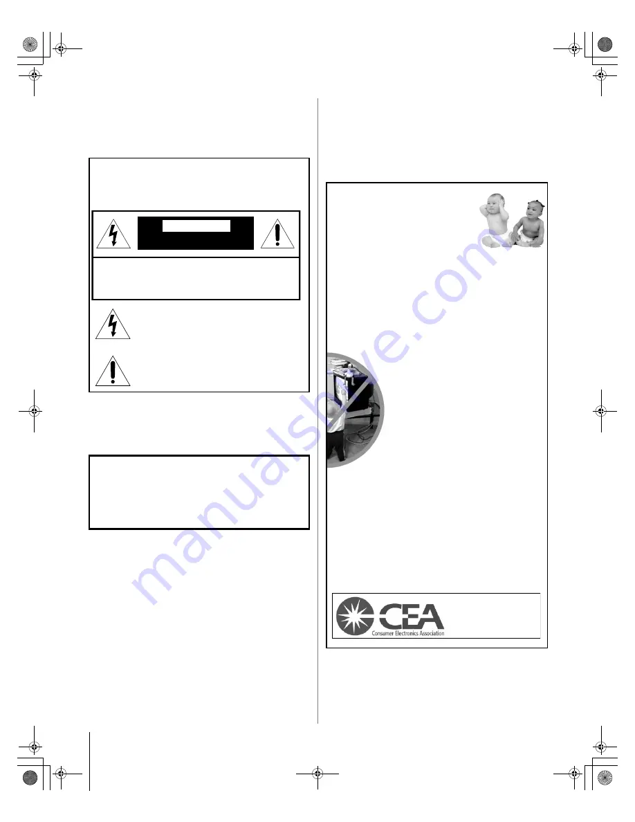
Child Safety

It Makes A Difference
Where Your TV Stands

Congratulations on your purchase! 
As you enjoy your new TV, keep these safety tips in mind:

The Issue

a

If you are like most consumers, you have a TV in your home. 
Many homes, in fact, have more than one TV.

a

The home theater entertainment experience is a growing trend, 
and larger TVs are popular purchases; however, they are not 
always supported on the proper TV stands.

a

Sometimes TVs are improperly secured or inappropriately 
situated on dressers, bookcases, shelves, desks, audio 

speakers, chests, or carts. As a result, TVs may fall over, 

causing unnecessary injury.

Toshiba Cares!

a

The consumer electronics industry 

is committed to making home entertainment 

enjoyable and safe.

a

The Consumer Electronics Association 
formed the Home Entertainment Support 
Safety Committee, comprised of TV and 

consumer electronics furniture 

manufacturers, to advocate children’s safety 

and educate consumers and their families 

about television safety.

Tune Into Safety

a

One size does NOT fit all! Use appropriate furniture large 

enough to support the weight of your TV (and other electronic 
components).

a

Use appropriate angle braces, straps, and anchors to secure your 
furniture to the wall (but never screw anything directly into the TV).

a

Carefully read and understand the other enclosed 
instructions for proper use of this product.

a

Do not allow children to climb on or play with furniture and TVs.

a

Avoid placing any item on top of your TV (such as a VCR, remote 
control, or toy) that a curious child may reach for.

a

Remember that children can become excited while watching 
a program and can potentially push or pull a TV over.

a

Share our safety message about this hidden hazard of the home 
with your family and friends. Thank you!

Safety Precautions

WARNING

TO REDUCE THE RISK OF FIRE OR 

ELECTRIC SHOCK, DO NOT EXPOSE THIS APPLIANCE 
TO RAIN OR MOISTURE.

The lightning flash with arrowhead symbol, within an 
equilateral triangle, is intended to alert the user to the 
presence of uninsulated “dangerous voltage” within 
the product’s enclosure that may be of sufficient 
magnitude to constitute a risk of electric shock to 
persons.

The exclamation point within an equilateral triangle is 
intended to alert the user to the presence of important 
operating and maintenance (servicing) instructions in 
the literature accompanying the appliance.

WARNING

: If you decide to wall mount this television, 

always use a UL-approved wall bracket appropriate for the 
size and weight of this television. The use of any wall bracket 
other than a UL-approved wall bracket appropriate for the 
size and weight of this television for wall mounting this 
television could result in serious bodily injury and/or property 
damage.

WARNING

RISK OF ELECTRIC SHOCK

DO NOT OPEN.

WARNING: TO REDUCE THE RISK OF ELECTRIC
SHOCK, DO NOT REMOVE COVER (OR BACK).
NO USER-SERVICEABLE PARTS INSIDE. REFER
SERVICING TO QUALIFIED SERVICE PERSONNEL.

2500 Wilson Blvd.
Arlington, VA 22201 U.S.A.
Tel. 703-907-7600 Fax 703-907-7690
www.CE.org

CEA is the Sponsor, Producer and

Manager of the International CES

®

196LCD_Inst.book  Page 2  Friday, May 26, 2006  11:19 AM

Summary of Contents for 47LX196

Page 1: ...42LX196 47LX196 42HL196 YC M VX1A000106A0 Integrated High Definition LCD Television 2006 TOSHIBA CORPORATION All Rights Reserved 196LCD_Inst_COV fm Page 1 Thursday August 17 2006 2 37 PM ...

Page 2: ...urniture large enough to support the weight of your TV and other electronic components a Use appropriate angle braces straps and anchors to secure your furniture to the wall but never screw anything directly into the TV a Carefully read and understand the other enclosed instructions for proper use of this product a Do not allow children to climb on or play with furniture and TVs a Avoid placing an...

Page 3: ...e the TV contains glass and a toxic liquid If the liquid comes in contact with your mouth or eyes or your skin is cut by broken glass rinse the affected area thoroughly with water and consult your doctor ALWAYS contact a service technician to inspect the TV any time it has been damaged or dropped 15 CAUTION To reduce the risk of electric shock do not use the polarized plug with an extension cord r...

Page 4: ...you leave the TV unattended or unused for long periods of time 33 During normal use the TV may make occasional snapping or popping sounds This is normal especially when the unit is being turned on or off If these sounds become frequent or continuous unplug the power cord and contact a Toshiba Authorized Service Center 34 WARNING RISK OF SERIOUS PERSONAL INJURY OR EQUIPMENT DAMAGE Never strike the ...

Page 5: ...S video and a cable box 12 Connecting an HDMI or DVI device to the HDMI input 13 Connecting a camcorder 14 Connecting a digital audio system 14 Connecting an analog audio system 15 G LINK connection 16 Connecting a personal computer PC 17 Connecting a home network 18 Connection diagrams for model 42HL196 20 Connecting a VCR and antenna or Cable TV no Cable box 20 Connecting a VCR and a Cable box 2...

Page 6: ...r TV to your antenna and equipment 2 The separate Operating Guide provides step by step instructions for using your TV s many features 3 The separate TV Guide On Screen Interactive Program Guide explains how to set up and navigate the TV Guide On Screen system in your TV Note Screen illustrations provided in this Installation Guide may not match the screens on your TV Please refer to your Operatin...

Page 7: ...Interface cable is for use with devices with HDMI output HDMI cable delivers digital audio and video in its native format HDMI cable carries both video and audio information therefore separate audio cables are not required for a complete HDMI device connection page 13 Note HDMI cable provides better picture performance than a standard composite video or S video cable Dual wand IR blaster G LINK ca...

Page 8: ... VCR first and or to ANT 2 the TV may not receive the signals correctly Always use the EJECT button to remove the CableCARD Removing the CableCARD without pressing EJECT can damage the CableCARD and or TV Such damage is NOT covered under your Toshiba warranty Never insert any object or card other than a CableCARD including without limitation a PCMCIA card into the CableCARD slot Always make sure t...

Page 9: ...the Operating Guide Chapter 2 In the United States TV GUIDE and other related marks are registered marks of Gemstar TV Guide International Inc and or one of its affiliates In Canada TV GUIDE is a registered mark of Transcontinental Inc and is used under license by Gemstar TV Guide International Inc IN from ANT VIDEO AUDIO OUT to TV L R R L OUT IN OUT OUT IN CH 3 CH 4 Stereo VCR From Cable TV or an...

Page 10: ...e VCR Turn ON the VCR Select the VIDEO 1 video input source on the TV To select the video input source press INPUT on the remote control Operating Guide To program the TV remote control to operate other devices see the Operating Guide Chapter 2 IN from ANT VIDEO AUDIO OUT to TV L R R L OUT IN CH 3 CH 4 IN OUT CH 3 CH 4 OUT OUT IN Stereo VCR TV upper back panel TV lower back panel Cable box From Ca...

Page 11: ...IDEO 2 on the side panel If your DVD player has HDMI video see page 13 Note The VIDEO AUDIO OUT terminals output signals from the ANT 1 ANT 2 VIDEO 1 and VIDEO 2 terminals when the appropriate input mode is selected To view antenna or Cable channels Select the ANT 1 video input source on the TV To view the DVD player Turn ON the DVD player Select the ColorStream HD 1 video input source on the TV T...

Page 12: ...or model 42HL196 see illustration on page 21 To use the TV Guide On Screen recording features if applicable to your TV model 1 Connect the G LINK cable according to the instructions on page 16 2 Make sure the VCR is connected to the VIDEO AUDIO OUT terminals on the TV see illustration 3 Set the VCR to the appropriate line input refer to your VCR owner s manual for details and then turn OFF the VCR...

Page 13: ... of standard analog audio cables per DVI device An HDMI to DVI adapter cable transfers video only Separate analog audio cables are required see illustration See Setting the HDMI audio mode in the Operating Guide Note For model 42HL196 see illustration on page 21 Note To ensure that the HDMI or DVI device is reset properly it is recommended that you follow these procedures When turning on your elec...

Page 14: ...ut Format field select either Dolby Digital or PCM depending on your device Selecting the optical audio output format in the Operating Guide 5 Turn off the TV s built in speakers in the same Audio Setup menu for 42LX196 and 47LX196 only Also see Turning off the built in speakers in the Operating Guide Note Some audio systems may not be compatible with Dolby Digital bitstream signals Older audio sy...

Page 15: ...LX196 only You will need standard audio cables To control the audio 1 Turn on the TV and the stereo amplifier 2 Turn off the TV s built in speakers Turning off the built in speakers in the Operating Guide Note To hear sound when using an external audio amplifier the volume of both the TV and the amplifier must be set to a reasonable listening level LINE IN L R TV upper back panel Analog audio ampl...

Page 16: ...e G LINK terminal 1 Locate the infrared sensor on the front of your VCR or Cable box The sensor is marked on some devices 2 Align one of the G LINK IR blaster cable s wands about 1 inch away from the infrared sensor on the front of the VCR and attach it using double sided mounting tape If you have a Cable box attach the other wand in a similar manner See illustration Note If you do not have a Cabl...

Page 17: ...re Using the PC setting feature in the Operating Guide Note Some PC models cannot be connected to this TV An adapter is not needed for computers with a DOS V compatible mini D sub15 pin terminal Depending on the DVD s title and the specifications of the PC on which you are playing the DVD Video some scenes may be skipped or you may not be able to pause during multi angle scenes Never connect a PC ...

Page 18: ...home network feature is compatible only with Microsoft Windows 2000 and the Home or Professional version of Microsoft Windows XP Service Pack 1 and Service Pack 2 See the Operating Guide for details The TV s home network connection allows access to file sharing only You will NOT be able to use the TV to access the Internet If you use an Ethernet crossover cable to connect your PC directly to the T...

Page 19: ...1 Your router switch may be part of your DSL or cable modem Your switch may be separate from your router For assistance contact your ISP or an IT professional 2 Coaxial or telephone cable depending on your modem type 3 Standard Ethernet RJ 45 cable 4 Do NOT connect a phone jack directly to the TV s RJ 45 Ethernet port 3 2 3 4 3 1 TV lower back panel Modem DSL or cable Router switch PC Cable or pho...

Page 20: ... ANT VIDEO AUDIO OUT to TV L R R L OUT IN OUT OUT IN CH 3 CH 4 Stereo VCR From Cable TV or antenna Signal splitter TV upper back panel TV lower back panel IN from ANT VIDEO AUDIO OUT to TV L R R L OUT IN IN OUT CH 3 CH 4 CH 3 CH 4 OUT OUT IN Stereo VCR Cable box From Cable TV TV upper back panel TV lower back panel Signal splitter 196LCD_Inst book Page 20 Friday May 26 2006 11 19 AM ...

Page 21: ... OUT AUDIO OUT COMPONENT VIDEO L R Satellite IN PB PR Y S VIDEO OUT CH 3 CH 4 IN From antenna Satellite receiver with component video Stereo VCR Signal splitter From satellite dish DVD player with component video TV upper back panel TV lower back panel IN from ANT VIDEO AUDIO OUT to TV L R R L OUT IN IN OUT CH 3 CH 4 CH 3 CH 4 OUT OUT IN Stereo VCR Cable box From Cable TV TV upper back panel TV lo...

Page 22: ...213 276 Connecting your TV Connecting a personal computer PC Conversion adapter if necessary PC audio cable PC audio output Computer TV upper back panel TV lower back panel 196LCD_Inst book Page 22 Friday May 26 2006 11 19 AM ...

Page 23: ...Audio Out 14 Dolby Digital 14 DSL modem 19 DVD player connection 11 21 DVI connection 13 21 E Ethernet RJ 45 cable 7 G G LINK connection 16 H HDMI cable 7 HDMI connection 13 21 Home network connection 18 I Installation care and service 3 O Optical audio cable 7 P PC connection 17 22 R RJ 45 THINC connection 18 Router 19 S Safety 2 Service 4 S video cable 7 V VCR connection 9 10 11 12 20 21 Video c...

Page 24: ...erica Consumer Products L L C MANUFACTURED BY HEAD OFFICE 191 McNABB STREET MARKHAM ONTARIO L3R 8H2 CANADA TEL 905 470 5400 SERVICE CENTERS TORONTO 191 McNABB STREET MARKHAM ONTARIO L3R 8H2 CANADA TEL 905 470 5400 MONTREAL 18050 TRANS CANADA KIRKLAND QUEBEC H9J 4A1 CANADA TEL 514 390 7766 VANCOUVER 13551 COMMERCE PARKWAY SUITE 110 RICHMOND B C V6V 2L1 CANADA TEL 604 303 2500 196 LCD Inst E F Web 2...

Reviews: