


- 14 -
ITEM
ADJUSTMENT PROCEDURE
1. Call up the adjustment mode display, then select the item
WID
.
2. Press the VOLUME
t
button to get the picture so the left
or right edges of raster begins to lack.
3. Press the VOLUME
s
button to advance the data by 12
steps.
Note : Check the horizontal picture position is correct.
WIDTH
(WID)
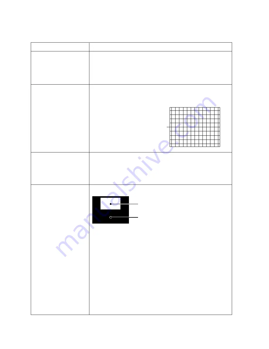
VERTICAL LINEARITY
(VLIN)
1. Call up the adjustment mode display, then select the item
VLIN
.
2. Receive the cross-hatch pattern which appears on the screen by the signal
generator.
3. Press the VOLUME
s
or
t
button to
obtain the picture of the best linearity
Center
1. Call up the adjustment mode display, then select the item
HIT
.
2. Press the VOLUME
t
button to get the picture so the top or bottom of
raster begins to lack.
3. Press the VOLUME
s
button to advance the data by 11 steps.
Note : Check the vertical picture position is correct.
Black and White pattern
High light area
Adjust "RDRV" or "BDRV" to be white.
Low light area
Fine adjust "RCUT", "GCUT" or "BCUT" to be black.
1. Set user control to reset position.
(
CONTRAST
→
Max
BRIGHTNESS, COLOR, TINT
→
Center.
)
2. Call up the adjustment mode display, then select the item RCUT.
3. Adjust the data of items
RCUT
,
GCUT
, and
BCUT
to "40H".
4. Press the -/-- button on Remote. (Y-MUTE : ON)
5. Gradually rotate R, G and B screen volume of FOCUS PAC clockwise or coun-
terclockwise until the raster appears slightly on the CRT through the each lens,
and leave them.
(Lookin to the lens in order to check the raster.)
6. Press the -/-- button on Remote. (Return to Normal Picture)
7. Press the
a
button on Remote, and select the Black and White pattern.
8. Adjust the data of items
RCUT
,
GCUT
and
BCUT
for proper white-balanced
picture in low light area.
9. Adjust the data of items
RDRV
and
BDRV
for proper white-balanced picture in
high light area.
10. Check the white balance in both low and high light areas.
If necessary, perform again steps from 8 to 9.
ELECTRICAL ADJUSTMENT
HEIGHT
(HIT)
WHITE BALANCE
(RCUT)
(GCUT)
(BCUT)
(RDRV)
(BDRV)
Summary of Contents for 43VJ33Q
Page 28: ... 28 LOCATION OF CONTROLS Power Button RED Power On Power Button RED Power On 43VJ33Q 50VJ33Q ...
Page 31: ... 31 K502 K501 Labels K601 A004 A420 A201 K101 K102 K103 A424 A225 A258 MECHANICAL DISASSEMBLY ...
Page 45: ... 46 45 SIGNAL BOARD PD0817E U902 BOTTOM FOIL SIDE ...
Page 46: ... 48 47 DEF CONV BOARD PD0818B U904 BOTTOM FOIL SIDE ...
Page 47: ... 50 49 POWER BOARD PD0819B U903 BOTTOM FOIL SIDE ...
Page 54: ......


