Nov. 1997 © TOSHIBA
17 - 31
3560/70 INSTALLATION
17.3 Key Copy Counter MU-8/MU-10
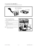
To install the key copy counter, the following parts are required:
• MU-10 Counter socket
• MU- 8
Key copy counter
Counter socket
• MU-10
Key copy counter
• MU-8
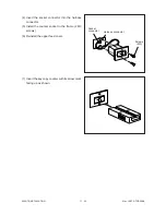
(1) Remove the upper feed cover.
Cut the window for the counter.
(2) Remove the blind plate (1 screw) for the 200V
machine.
(3) Pull out the harness connector from the open-
ing in the machine frame.
Disconnect the short connector from the har-
ness.
Note: Remove the rear cover if the harness con-
nector is in the back etc.
Screw holes for the socket
Harness connector
Blind plate
Summary of Contents for 3560
Page 21: ...3560 70 GENERAL 2 14 Nov 1997 TOSHIBA B Location diagram for lower unit ...
Page 72: ...Nov 1997 TOSHIBA 13 25 3560 70 CIRCUIT DIAGRAMS 13 3 Power Supply Circuit PS ACC A 115 V ...
Page 73: ...3560 70 CIRCUIT DIAGRAMS 13 26 Nov 1997 TOSHIBA B 230 V ...
Page 77: ...Nov 1997 TOSHIBA 15 1 3560 70 PC BOARD 15 PC BOARD ASSEMBLY 15 1 PWA LGC ...
Page 78: ...3560 70 PC BOARD 15 2 Nov 1997 TOSHIBA 15 2 PWA PNL ...
Page 79: ...Nov 1997 TOSHIBA 15 3 3560 70 PC BOARD 15 3 PWA KEY KEY1 KEY2 ...
Page 80: ...3560 70 PC BOARD 15 4 Nov 1997 TOSHIBA 15 4 PWA ERS ...
Page 81: ...Nov 1997 TOSHIBA 15 5 3560 70 PC BOARD 15 5 PS ACC A 1 115V ...
Page 82: ...3560 70 PC BOARD 15 6 Nov 1997 TOSHIBA A 2 230V ...

