


6
NOTE
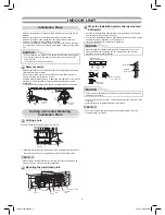
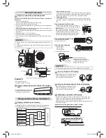
If the pipe is bent incorrectly, the indoor unit may unstably be set on the wall.
After passing the connecting pipe through the pipe hole, connect the
connecting pipes to the auxiliary pipes and wrap the facing tape around
them.
CAUTION
Indoor Unit Fixing
• For detaching the indoor unit from the
installation plate, pull the indoor unit
toward you while pushing its bottom up at
the speci
fi
ed parts.
1
2
1
1. Pass the pipe through the hole in the wall and hook the indoor unit on the
installation plate at the upper hook.
2. Swing the indoor unit to right and left to con
fi
rm that it is
fi
rmly hooked up
on the installation plate.
3. While pressing the indoor unit onto the wall, hook it at the lower part on the
installation plate. Pull the indoor unit toward you to con
fi
rm that it is
fi
rmly
hooked up on the installation plate.
Drainage
1. Run the drain hose sloped downwards.
2. Put water in the drain pan and make sure that the water is drained out of
doors.
3. When connecting extension drain hose, insulate the connecting part of
extension drain hose with shield pipe.
NOTE
• The hole should be made at a slight downward slant on the outdoor side.
Arrange the drain pipe for proper drainage from the unit.
Improper drainage can result in dew-dropping.
This air conditioner has the structure designed
to drain water collected from dew, which forms
on the back of the indoor unit, to the drain pan.
Therefore, do not store the power cord and other
parts at a height above the drain guide.
CAUTION
OUTDOOR UNIT
OUTDOOR UNIT
Installation Place
• A place which provides enough spaces around the outdoor unit as shown in
the diagram
• A place which can bear the weight of the outdoor unit and does not allow an
increase in noise level and vibration
• A place where the operation noise and discharged air do not disturb your
neighbors
• A place which is not exposed to a strong wind
• A place free of a leakage of combustible gases
• A place which does not block a passage
• When the outdoor unit is to be installed in an elevated position, be sure to
secure its feet.
• An allowable length of the connecting pipe is up to 20 m.
• There is no need to add refrigerant as long as the length of the connection
piping is 15 m or less.
• You will need to add 20g of refrigerant per meter of added connection piping
for installations requiring connection piping to be between 16 m to 20 m.
• An allowable height level is up to 10 m.
• A place where the drain water does not cause any problems
CAUTION
1. Install the outdoor unit in a location where there are no obstructions near
its air intake or air outlet.
2. When the outdoor unit is installed in a place that is always exposed to
strong winds like on the coast or on a high story of a building, secure the
normal fan operation using a duct or a wind shield.
3. Especially in windy areas, install the unit to prevent the admission of wind.
4. Installation in the following places may result in trouble. Do not install the
unit in such places.
• A place full of machine oil.
• A saline-place such as the coast.
• A place full of sul
fi
de gas.
• A place where high-frequency
waves are likely to be generated,
such as from audio equipment,
welders, and medical equipment.
• Do not use the supplied drain nipple for draining water. Drain the water from
all the drain holes directly.
• To protect the outdoor unit from snow accumulation, install a holding frame,
and attach a snow protection hood and plate.
* Do not use a double-stacked design.
Precautions about Installation in Regions
with Snowfall and Cold Temperatures
• Bind the auxiliary pipes (two) and connecting cable with facing tape
tightly. In case of leftward piping and rear-leftward piping, bind the
auxiliary pipes (two) only with facing tape.
Indoor unit
Connecting cable
Auxiliary pipes
Installation plate
• Carefully arrange pipes so that any pipe does not stick out of the rear
plate of the indoor unit.
• Carefully connect the auxiliary pipes and connecting pipes to one
another and cut off the insulating tape wound on the connecting pipe
to avoid double-taping at the joint; moreover, seal the joint with the
vinyl tape, etc.
• Since dewing results in a machine trouble, make sure to insulate both
connecting pipes. (Use polyethylene foam as insulating material.)
• When bending a pipe, carefully do it, not to crush it.
The lower part of indoor unit may
fl
oat,
due to the condition of piping and you
cannot
fi
x it to the installation plate. In
that case, use the
%
screws provided
to
fi
x the unit and the installation plate.
Information
%
Screw
%
Screw
Hook here.
Installation plate
Hook
Press
(unhook)
Push
Push
Do not rise the
drain hose.
Do not form the
drain hose into
a wavy shape.
50 mm
or more
Do not put the
drain hose end
into water.
Do not put the
drain hose end
in the drainage ditch.
Shield pipe
Drain hose
Extension drain hose
Inside the room
Wall
Drain
guide
Space for pipes
Snow protection plate
Snow protection hood
At least
50 cm
Snow accumulation line
Holding frame
Front
Anchor
bolts
Install at least 50 cm
above the snow
accumulation line.
Strong
wind
1110651154-EN.indd 6
1110651154-EN.indd 6
2/15/10 9:39:40 AM
2/15/10 9:39:40 AM