


– 21 –
Location
Parts No.
Description
No.
Location
Parts No.
Description
No.
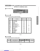
SPECIFIC INFORMATIONS
Q421B
70391355
SCREW, BIND HEAD TAP-TITE B,
BITTB 3X8 SZN
Q422
23904521
IC, AN7805
Q422B
70391355
SCREW, BIND HEAD TAP-TITE B,
BITTB 3X8 SZN
Q430
23314141
TRANSISTOR, 2SC3852
Q431
23114459
TRANSISTOR, RN1205
Q470
23114541
TRANSISTOR, 2SA1320
Q610
23000867
IC, AN5274
Q610B
70391355
SCREW, BIND HEAD TAP-TITE B,
BITTB 3X8 SZN
Q612
23314962
TRANSISTOR, KTA1266 Y
Q620
23114478
TRANSISTOR, RN2004
Q621
23314965
TRANSISTOR, KTC3198 Y
Q801
23009322
IC, POW SW.REG.IC VDS=650V,
PO= STR-G8656
Q801B
70391355
SCREW, BIND HEAD TAP-TITE B,
BITTB 3X8 SZN
Q805
23114459
TRANSISTOR, RN1205
Q811
23318299
IC, L78MR05-FA
Q811B
70391355
SCREW, BIND HEAD TAP-TITE B,
BITTB 3X8 SZN
Q818
23114469
TRANSISTOR, RN2201
Q819
23314965
TRANSISTOR, KTC3198 Y
Q820
23314965
TRANSISTOR, KTC3198 Y
*
Q826
23906937
IC, PHOTO COUPLER, ON3171-R
Q901
23314780
TRANSISTOR, 2SC4544
Q902
23314965
TRANSISTOR, KTC3198 Y
Q903
23314780
TRANSISTOR, 2SC4544
Q904
23314965
TRANSISTOR, KTC3198 Y
Q905
23314780
TRANSISTOR, 2SC4544
Q906
23314965
TRANSISTOR, KTC3198 Y
Q907
23314962
TRANSISTOR, KTA1266 Y
Q908
23114429
TRANSISTOR, 2SC2120-Y(TE
QA02
23906922
IC, CAT24WC04P
QA51
23314965
TRANSISTOR, KTC3198 Y
QA52
23314962
TRANSISTOR, KTA1266 Y
QA53
23314962
TRANSISTOR, KTA1266 Y
QA60
23314965
TRANSISTOR, KTC3198 Y
QB30
23314965
TRANSISTOR, KTC3198 Y
QB43
23114459
TRANSISTOR, RN1205
QB60
23314965
TRANSISTOR, KTC3198 Y
QB61
23314965
TRANSISTOR, KTC3198 Y
QS01
23114623
TRANSISTOR, 2SC2878-A(TEM
QV10
23314962
TRANSISTOR, KTA1266 Y
QV13
23904943
IC, MM1111XS
QV23
23314965
TRANSISTOR, KTC3198 Y
D101
23316411
DIODE, ZENER, HZT33-12
D150
23115636
DIODE, ISS110
D224
23357341
DIODE, 1SS133
D301
23118094
DIODE, EU2A
D302
23118094
DIODE, EU2A
D303
23316794
DIODE, SC570A
D306
23357341
DIODE, 1SS133
D370
23118638
DIODE, ZENER, RD2.4ESA B1
D406
23118094
DIODE, EU2A
D408
23118094
DIODE, EU2A
D421
23118534
DIODE, ZENER, RD4.7ES B3
D431
23118622
DIODE, ZENER, RD10ES B2
D432
23357341
DIODE, 1SS133
D441
23118516
DIODE, ZENER, RD9.1ES B3
D444
23316254
DIODE, ERC06-15
D461
23118338
DIODE, RU4AM LF-K2
D467
23118094
DIODE, EU2A
D470
23118511
DIODE, ZENER, RD12ES B2
D473
23357341
DIODE, 1SS133
D612
23357341
DIODE, 1SS133
D622
23357341
DIODE, 1SS133
D801
23357237
DIODE, TS4B05G-A1
D805
23118094
DIODE, EU2A
D806
23118094
DIODE, EU2A
D808
23118526
DIODE, ZENER, RD6.8ES B2
D809
23118529
DIODE, ZENER, RD5.6ES B2
D812
23118094
DIODE, EU2A
D818
23118507
DIODE, ZENER, RD13ESA B3
D872
23118511
DIODE, ZENER, RD12ES B2
D883
23357336
DIODE, RL3A LF014-3
D885
23316714
DIODE, RL2Z
D901
23357341
DIODE, 1SS133
D903
23357341
DIODE, 1SS133
D904
23357341
DIODE, 1SS133
D905
23357341
DIODE, 1SS133
D906
23357341
DIODE, 1SS133
D907
23357341
DIODE, 1SS133
D908
23357341
DIODE, 1SS133
D909
23357341
DIODE, 1SS133
D910
23357341
DIODE, 1SS133
D911
23118095
DIODE, ERB44-06
DB01
23358566
LED, LAMP RED, L-2523IT
DB30
23357341
DIODE, 1SS133
MISCELLANEOUS
B202
23037312
SCREW, BTBW3X12SZN
E501
23198694
WIRE, CRT EARTH, 21D7DXE
E912
23848729
WEDGE, YOKE HOLDING, 3 REQUIRED
*
F470
23144874
FUSE, 250V 0.8A-T B/S MINI
F470A
23165433
FUSE HOLDER, 5.2 SOC
*
F801
23144508
FUSE, CARTRIDGE 5.2X20, 250V 4.0A
F801A
23165433
FUSE HOLDER, 5.2 SOC
G218
24366272
CARBON FILM, 1/6W 2.7K OHM J
G303
24321109
OXIDE METAL FILM, 1/2W 1 OHM J
G421
23118534
DIODE, ZENER, RD4.7ES B3
G805
23248234
COIL, CHOKE, TLN3481AC
G806
23248234
COIL, CHOKE, TLN3481AC
GJ01
24366472
CARBON FILM, 1/6W 4.7K OHM J
GJ02
24366472
CARBON FILM, 1/6W 4.7K OHM J
GL511
23289100
COIL, PEAKING, TRF4100AF
GL512
23103775
COIL, FERRITE CHOKE, TEM2014
GL512
23103248
COIL, FERRITR CHOKE, TEM2014AA
GR160 24366470
CARBON FILM, 1/6W 47 OHM J
KB01
23009125
IC, REMOTE PHOTO RECIEVER, RPM6938
M461A 23192943
ANODE CAP ASSEMBLY
M461B 23504358
CABLE, FOCUS
M461C 23504359
CABLE, SCREEN
N724
23965900
TAPE, GLASS-CLOTH, W/ADHESIVE
W=18 T=0.18
P661
23363607
JACK, HEAD PHONE, 3.5MM
*
P801
23372159
POWER CORD, CEE 250V 2.5A SILV 201
(21VZ3E)
*
P801
23372160
POWER CORD, SSA 127V15A 250V6A
CMC-02 (21VZ3M/21VZ3MJ)
P801A
23451788
HOLDER, POWER CORD, 1450TE
P802
23368249
POWER CORD, 2P 11.88MM VH-JST
P900
23164725
CONNECTOR, PLUG 2P
P910
23164725
CONNECTOR, PLUG 2P
PB11A
23713013
BASE SOCKET 16P 1.5
PB11B
23713014
CONNECTOR, BRIDGE PLUG 16P 1.5
PB12A
23713013
BASE SOCKET 16P 1.5
PB12B
23713014
CONNECTOR, BRIDGE PLUG 16P 1.5
PV01
23023036
JACK, PIN 0S4P MSP-226V22-19 NI
PV02
23023047
JACK, PIN JACK 2P KUN KM04036C01-01
*
S801
23344481
SWITCH, POWER, AAPY2211
SA01
23344443
SWITCH, TACTING SWITCH TSV TYP TSVB-1
SA02
23344443
SWITCH, TACTING SWITCH TSV TYP TSVB-1


