


Location
Parts No.
Description
No.
Location
Parts No.
Description
No.
– 17 –
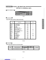
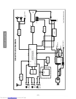
SPECIFIC INFORMATIONS
CAPACITORS
C101
24794101
ELECTROLYTIC, 16V 100UF M
C102
24794221
ELECTROIYTIC, 16V 220UF M
C106
24796479
ELECTROLYTIC, 35V 4.7UF M
C108
24539474
PLASTIC FILM, 50V 0.47UF J
C109
24794100
ELECTROLYTIC, 16V 10UF M
C116
24232103
CERAMIC DISC, 50V F 0.01UF Z
C118
24474102
CERAMIC, 50V B 1000PF K
C120
24794100
ELECTROLYTIC, 16V 10UF M
C121
24232103
CERAMIC DISC, 50V F 0.01UF Z
C123
24797010
ELECTROLYTIC, 50V 1UF M
C129
24474102
CERAMIC, 50V B 1000PF K
C130
24797479
ELECTROLYTIC, 50V 4.7UF M
C131
24232103
CERAMIC DISC, 50V F 0.01UF Z
C132
24232103
CERAMIC DISC, 50V F 0.01UF Z
C133
24232103
CERAMIC DISC, 50V F 0.01UF Z
C135
24212222
CERAMIC DISC, 50V B 2200PF K
C136
24206228
ELECTROLYTIC, 50V 0.22UF M 7L 3A
C137
24212103
CERAMIC DISC, 50V B 10000PF K
C138
24794470
ELECTORLYTIC, 16V 47UF M
C141
24436101
CERAMIC DISC, 50V SL 100PF J
C150
24232103
CERAMIC DISC, 50V F 0.01UF Z
C166
24232103
CERAMIC DISC, 50V F 0.01UF Z
C167
24794101
ELECTROLYTIC, 16V 100UF M
C170
24232103
CERAMIC DISC, 50V F 0.01UF Z
C171
24794100
ELECTROLYTIC, 16V 10UF M
C172
24794100
ELECTROLYTIC, 16V 10UF M
C173
24794100
ELECTROLYTIC, 16V 10UF M
C174
24436330
CERAMIC DISC, 50V SL 33PF J
C175
24436330
CERAMIC DISC, 50V SL 33PF J
C176
24436330
CERAMIC DISC, 50V SL 33PF J
C187
24232103
CERAMIC DISC, 50V F 0.01UF Z
C188
24797100
ELECTROLYTIC, 50V 10UF M
C189
24797478
ELECTROLYTIC, 50V 0.47UF M
C192
24797478
ELECTROLYTIC, 50V 0.47UF M
C216
24797010
ELECTROLYTIC, 50V 1UF M
C224
24794100
ELECTROLYTIC, 16V 10UF M
C226
24539104
PLASTIC FILM, 50V 0.1UF J
C227
24539104
PLASTIC FILM, 50V 0.1UF J
C231
24232103
CERAMIC DISC, 50V F 0.01UF Z
C232
24232103
CERAMIC DISC, 50V F 0.01UF Z
C305
24617915
ELECTROLYTIC, 50V 1UF K 3A LI
C306
24794102
ELECTROLYTIC, 16V 1000UF M
C307
24693473
PLASTIC FILM, 100V 0.047UF J
C308
24796101
ELECTROLYTIC, 35V 100UF M
C312
24796102
ELECTROLYTIC, 35V 1000UF M
C313
24797478
ELECTROLYTIC, 50V 0.47UF M
C313
24082057
PLASTIC FILM, 100V 220000PF J
C314
24212152
CERAMIC DISC, 50V B 1500PF K
C317
24214471
CERAMIC DISC, 500V B 470PF K
C320
24796101
ELECTROLYTIC, 35V 100UF M
C370
24794101
ELECTROLYTIC, 16V 100UF M
C371
24794220
ELECTROLYTIC, 16V 22UF M
C410
24082256
PLASTIC FILM, 100V 2200PF J
C413
24214182
CERAMIC DISC, 500V B 1800PF K
C416
24678229
ELECTROLYTIC, 200V 2.2UF M 3A
C417
24214391
CERAMIC DISC, 500V B 390PF K
C420
24795220
ELECTROLYTIC, 25V 22UF M
C421
24666470
ELECTORLYTIC, 16V 47UF M 3A
C431
24797479
ELECTROLYTIC, 50V 4.7UF M
C432
24794100
ELECTROLYTIC, 16V 10UF M
C433
24232103
CERAMIC DISC, 50V F 0.01UF Z
C434
24232103
CERAMIC DISC, 50V F 0.01UF Z
C435
24794471
ELECTROLYTIC, 16V 470UF M
C436
24797478
ELECTROLYTIC, 50V 0.47UF M
C437
24212822
CERAMIC DISC, 50V B 8200PF K
C440
24082555
PLASTIC FILM, 1500VH 1000PF H
C442
24082430
PLASTIC FILM CF92 T 250V R33UF J
C443
24667102
ELECTROLYTIC, 25V 1000UF M 3A
C444
24082590
PLASTIC FILM CF92 T 1500VH 9100PF H
C445
24828563
PLASTIC FILM, 200V 56000PF J
C447
24679100
ELECTROLYTIC, 250V 10UF M 3A
C448
24640908
ELECTROLYTIC, 160V 33UF M 3A LI
C463
24214222
CERAMIC DISC, 500V B 2200PF K
C464
24640872
ELECTROLYTIC, 100V 10UF M 3A
C467
24829433
PLASTIC FILM, 400V 43000PF J
C470
24794220
ELECTROLYTIC, 16V 22UF M
C481
24539474
PLASTIC FILM, 50V 0.47UF J
C484
24539104
PLASTIC FILM, 50V 0.1UF J
C485
24539104
PLASTIC FILM, 50V 0.1UF J
C491
24591223
PLASTIC FILM, 50V 0.022UF J
C502
24591103
PLASTIC FILM, 50V 0.01UF J
C516
24232103
CERAMIC DISC, 50V F 0.01UF Z
C517
24794101
ELECTROLYTIC, 16V 100UF M
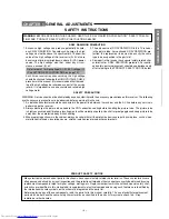
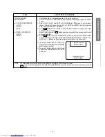
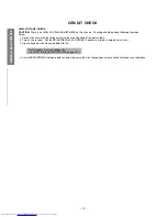
WARNING
: BEFORE SERVICING THIS CHASSIS, READ THE “X-RAY RADIATION PRECAUTION”, “SAFETY
PRECAUTION” AND “PRODUCT SAFETY NOTICE” ON PAGE 3 OF THIS MANUAL.
CAUTION
: The international hazard symbols “
” in the schematic diagram and the parts list designate com-
ponents which have special characteristics important for safety and should be replaced only with types identical to
those in the original circuit or specified in the parts list. The mounting position of replacements is to be identical with
originals. Before replacing any of these components, read carefully the PRODUCT SAFETY NOTICE. Do not
degrade the safety of the receiver through improper servicing.
NOTICE:
•
The part number must be used when ordering parts, in order to assist in processing, be sure to include the Model
number and Description.
•
The PC board assembly with
*
mark is no longer available after the end of the production.
Model : 21VZ3E/21VZ3M/21VZ3MJ
Capacitors ............. CD
:
Ceramic Disk
PF
:
Plastic Film
EL
:
Electrolytic
Resistors ............... CF
:
Carbon Film
CC
:
Carbon Composition
MF
:
Metal Film
OMF :
Oxide Metal Film
VR
:
Variable Resistor
FR
:
Fusible Resistor
(All CD and PF capacitors are
±
5%, 50V and all resistors,
±
5%, 1/6W unless otherwise noted.)
CHASSIS AND CABINET REPLACEMENT PARTS LIST


