


6
For adjustments of this model, the bus data is converted to various analog signals by the D/A converter
circuit.
Note: There are still a few analog adjustments in this series such as focus and master screen voltage.
Follow the steps below whenever the service adjustment is required. See "Table-B" to determine, if serv-
ice adjustments are required.
1. Service mode
Before putting unit into the service mode, check that
customer adjustments are in the normal mode. Use
the reset function in the video adjustment menu to
ensure customer controls are in their proper (reset)
position.
2. Service item selection
Once in the service mode, press the Ch-up or Ch-
down button on the remote controller or at the set.
The service adjustment item will vary in increments
of one. Select the item you wish to adjust.
3. Data number selection
Press the Vol-up or down button to adjust the data
number.
To enter the service mode and exit serv-
ice mode.
Short JA137&JA138 for 1 Second and release to switch
to the service mode position, and the microprocessor is
in input mode.(Adjustment through the I
2
C bus control.)
To exit the service mode, turn the television off by
pressing the power button.
25
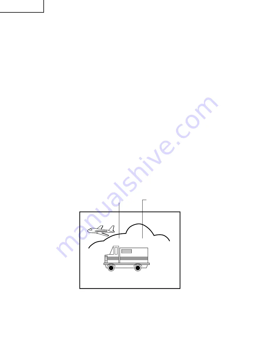
AGC:
DATA NUMBER
SERVICE ADJUSTMENT ITEM
Figure A.
20AR33
Summary of Contents for 20AR33
Page 15: ...14 6 5 4 3 2 1 A B C D E F G H BLOCK DIAGRAM 1 20AR33 ...
Page 16: ...15 6 5 4 3 2 1 A B C D E F G H SCHEMATIC DIAGRAM CRT Unit 20AR33 ...
Page 17: ...16 A B C D E F G H MODEL 20AR33 BLOCK DIAGRAM 2 20AR33 ...
Page 18: ...17 20AR33 ...
Page 19: ...18 20AR33 ...
Page 20: ...19 20AR33 ...
Page 21: ...20AR33 20 ...
Page 22: ...20AR33 21 ...
Page 23: ...22 6 5 4 3 2 1 A B C D E F G H MODEL 20AR33 CHASSIS LAYOUT 20AR33 ...
Page 25: ...24 6 5 4 3 2 1 A B C D E F G H PWB A MAIN Unit Chip Parts Side 20AR33 ...
Page 36: ...TOSHIBA CORPORATION 1 1 SHIBAURA 1 CHOME MINATO KU TOKYO 105 8001 JAPAN ...


