


11
Ë
SERVICE ADJUSTMENT
RF AGC Adjustment
1. Receive a good local channel.
2. Enter the service mode signal category and select
the service adjustment "AGC".
3. Set the data value to point where no noise or beat
appears.
4. Select another channel to confirm that no noise or
beat appears.
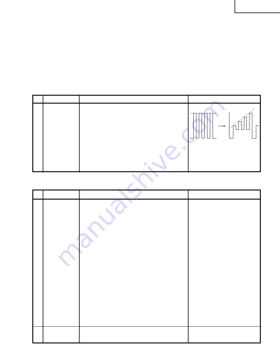
HORIZONTAL AND VERTICAL DEFLECTION LOOP ADJUSTMENT
No. Adjusting point
Adjusting procedure/conditions
Waveform and others
V-SLOPE(I
2
C
BUS CON-
TROL)
V-CENTER (I
2
C
BUS CON-
TROL)
V - AMP (I
2
C
BUS CON-
TROL)
S-CORREC-
TION (I
2
C BUS
CONTROL)
H - CENTER
1. Receive Monoscope Pattern Signal.
2. Call the "V-LIN" mode.
3. Increase or decrease "V-LIN" by Volume key till
the horizontal line in the center of monoscope is
just at the position where the blanking starts.
1. Call the "V-CENT" mode.
2. Increase or decrease "V-CENT" by Volume key till
the picture is centered.
1. Call the "V-AMP" mode.
2. Increase or decrease "V - AMP" by Volume key to
set overscan of 10.0% typical.
Adjustment Spec 10.0% range
±
1%.
FIXED DATA, NO NEED TO ADJUST.
1. Call the "H-CENT" mode.
2. Increase or decrease "H-CENT" by Volume key
to center the picture horizontal.
1
2
3
4
5
Focus
adjustment
1. Receive the "Monoscope Pattern" signal.
2. Press R/C to set Picture NORMAL condition.
3. Adjust the focus control to get the best focus.
6
No. Adjusting point
Adjusting procedure/conditions
Waveform and others
SUB-TINT (I
2
C
BUS CON-
TROL)
1. Receive the "Colour Bar" signal through AV in.
2. Connect the oscilloscope to TP853 (Pin (5) of
P882) BLUE-OUT.
»
Range
: 100mV/div. (AC)(Use Probe 10:1)
»
Sweep time : 10 µsec/div.
3. Call the "SUB-TINT" mode in service mode. Ad-
just the "SUB-TINT" bus data to obtain the wave-
form shown as Fig 1.
4. "SUB-TINT" bus data decrease 4 steps to get fi-
nal waveform. (Fig 2.)
5. Clear the SERVICE mode.
1
CHROMA ADJUSTMENT
FINAL WAVEFORM
Fig 2
WAVEFORM 1
Y CY G MG R B
W
SAME LEVEL
Fig 1
20AR33
Summary of Contents for 20AR33
Page 15: ...14 6 5 4 3 2 1 A B C D E F G H BLOCK DIAGRAM 1 20AR33 ...
Page 16: ...15 6 5 4 3 2 1 A B C D E F G H SCHEMATIC DIAGRAM CRT Unit 20AR33 ...
Page 17: ...16 A B C D E F G H MODEL 20AR33 BLOCK DIAGRAM 2 20AR33 ...
Page 18: ...17 20AR33 ...
Page 19: ...18 20AR33 ...
Page 20: ...19 20AR33 ...
Page 21: ...20AR33 20 ...
Page 22: ...20AR33 21 ...
Page 23: ...22 6 5 4 3 2 1 A B C D E F G H MODEL 20AR33 CHASSIS LAYOUT 20AR33 ...
Page 25: ...24 6 5 4 3 2 1 A B C D E F G H PWB A MAIN Unit Chip Parts Side 20AR33 ...
Page 36: ...TOSHIBA CORPORATION 1 1 SHIBAURA 1 CHOME MINATO KU TOKYO 105 8001 JAPAN ...


