background image

– 18 –

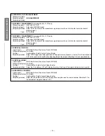
GENERAL ADJUSTMENTS

SPECIFIC INFORMATIONS

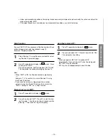
Manual Search

Select Position 12.
Press 

3

 repeatedly until 12 is displayed.

Or, press 

6

 twice to display “--” on the screen then

press the “1” and “2” buttons (

2

) in this order.

Press 

7

 repeatedly to display the  D5  screen. Press

8

 and select “SEARCH”. Press 

5

 to search. Pressing

“-” searches for channels at lower frequencies while
pressing “+” searches for channels at higher frequen-
cies.

When Channel 12 is found, press 

8

 to select “

a

”.

Press “+” 

5

 to complete the presetting.

Store Position

Select Position 12.
Press 

2

 or 

3

 to find the position preset for Channel

12.

When Channel 12 is selected, press 

7

 repeatedly to

display the  D5  screen. Press 

8

 and select “POSI-

TION”. Press 

5

 and set “POSITION” to P12.

Pressing  “-” and “+” respectively decreases and in-
creases the Position number.

When Channel 12 is found, press 

8

 to select

“MEMORY”. Press “+” 

5

 to complete the presetting.

PROGRAMMING CHANNEL MEMORY

For easy Channel selection, the chosen Position should have the same number as Channel stored there. For this
operation, you may use the “SEARCH” and “SKIP” functions.
Example : Presetting Channel 12 to Position 12

Channel Preset

Auto search memory (ASM)

All the channels that can be received are preset
automatically.

Select the starting position for ASM. Press 

2

 or 

3

.

Set the correct broadcast system for your region.
Press 

7

 repeatedly to call up the “SET UP” menu  D5.

Set “COLOR” to “AUTO” and set “SOUND” according
to the table on page 6 of Owner's Manual using 

8

 and

5

.

Select “ASM”, then press 

5

 (+) to start the search.

When the TV screen returns to the start position, the
procedure is complete.

1

2

3

1

2

3

1

2

3

Manual Search and Changing the assigned
position

Summary of Contents for 20A3VX

Page 1: ...SERVICE MANUAL COLOUR TELEVISION Dec 2003 FILE NO 040 200117 S1E Chassis 20A3VX ...

Page 2: ...ODE 6 DESIGN MODE 9 ELECTRICAL ADJUSTMENTS 10 CIRCUIT CHECK 15 CHAPTER 2 SPECIFIC INFORMATIONS SETTING ADJUSTING DATA 16 LOCATION OF CONTROLS 17 PROGRAMMING CHANNEL MEMORY 18 CHASSIS AND CABINET REPLACEMENT PARTS LIST 20 PC BOARDS BOTTOM VIEW 27 TERMINAL VIEW OF TRANSISTORS 30 CIRCUIT BLOCK DIAGRAM 32 SPECIFICATIONS End APPENDIX CIRCUIT DIAGRAM ...

Page 3: ...e attempted by anyone unfamiliar with the necessary precautions on this receiver The following are the necessary precautions to be observed before servicing this chassis 1 An isolation transformer should be connected in the power line between the receiver and the AC line before any service is performed on the receiver 2 Always discharge the picture tube anode to the CRT conductive coating before h...

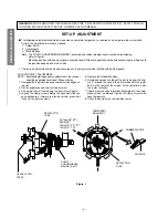
Page 4: ...ECTION YOKE TEMPORARY MOUNTING RUBBER WEDGE ADHESIVE DEFLECTION YOKE PURITY CONVERGENCE MAGNET ASS Y 29 1mm 28 29 25mm 25 19mm 19 20 21 14mm 13 14 Figure 1 COLOUR PURITY ADJUSTMENT NOTE Before attempting any purity adjustments the receiver should be operated for at least fifteen minutes 1 Demagnetize the picture tube and cabinet using a degauss ing coil 2 Set the brightness and contrast to maximum...

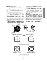
Page 5: ...1 Do not remove cover paper on adhesive part of the wedge 3 Tilt front of the deflection yoke up or down to obtain better convergence in circumference See figure 3 Push the mounted wedge into the space between picture tube and the yoke to fix the yoke temporarily 4 Put other wedge into bottom space and remove the cover paper to stick 5 Tilt front of the yoke right or left to obtain better conver g...

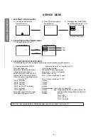
Page 6: ...data value Volume on TV or Remote Adjustment menu mode ON OFF MENU button on TV Initialization of the memory QA02 CALL Channel button on TV s Reset the count of operating protect circuit to 00 CALL Channel button on TV t RCUT selection 1 button GCUT selection 2 button BCUT selection 3 button CNTX or SCNT selection 4 button COLC selection 5 button TNTC selection 6 button Test audio signal ON OFF 1k...

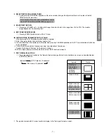
Page 7: ... item 2 Press and hold the CALL button on the Remote then press the CHANNEL s button on the TV The initialization of QA02 has been complated 3 Check the picture carefully If necessary adjust any adjustment item above Perform Auto search Memory on the owner s manual CAUTION Never attempt to initialize the data unless QA02 has been replaced 7 TEST SIGNAL SELECTION 1 Every pressing of a button on the...

Page 8: ...d colour of mode now selected Green and Red Indicated colour of other modes White Green Normal Red The microcomputer operates to provide judgement of no video signal The red colour is still indicated though the signal is input failure may exist in input signal line including QV01 QV01 In case of indication green Normal In case of indication red with input signal Failure may exist in output line in...

Page 9: ...ign mode changes the adjustment items in the order of table 3 s button for reverse order Refer to table 3 for data of design mode See SETTING ADJUSTING DATA on page 16 3 ADJUSTING THE DATA Pressing of VOLUME s or t button will change the value of data When QA02 is initialized items OPT0 and OPT1 of DESIGN MODE are set to the data of the representative model of this chassis family Therefore because...

Page 10: ... the difference between the belt of vertical retrace and the border of black portion of inside pattern is visible After that return vertical height and contrast ITEM ADJUSTMENT PROCEDURE Belt of vertical retrace HORIZONTAL POSITION ADJUSTMENT HPOS VERTICAL POSITION ADJUSTMENT VPOS 1 Set the TV in service mode and get black or white cross bar signal with VIDEO button on remote hand unit 2 Select ei...

Page 11: ...on screen Note Every pressing of button provides Horizontal line picture and Normal picture alternately 5 Press button to release horizontal line picture and select the two other colours which did not light in the above step with CHANNEL s t buttons Then tap VOLUME buttons so that three colours slightly light in the same level X To correct white balance in light area select GDRV and BDRV with CHAN...

Page 12: ...ay 2 0 1 0V at TP14 12 On screen display RFAGC OK Coil OK 13 Power Off AFT SPEC 2 5 0 5V TP13 AGC SPEC 2 0 1 0V TP14 2 SUB COLOUR CONTRAST SCNT Measuring point Adjusting signal NO ADJUSTMENT Adjusting method 3 SUB BRIGHT BRTC Adjusting signal Sub Bright PAL or NTSC signal Adjusting method 1 Set user control to the standard 1 2 Change BRTC data to set black collapse numbers by eye check SPEC 4 1 5 ...

Page 13: ...ial value 20H GCUT Initial value 20H BCUT Initial value 20H 3 Set the mode to the one horizontal line mode MUTE BRIGHT 4 Change SCREEN VR to set it so that one of the line R G and B will light slightely 5 Change CUT OFF data to set it so that each one of R G and B will light slighty for about white 6 Release the H Line mode 7 Change B G drive data and R G B CUT OFF data to adjust white balance in ...

Page 14: ...WG Philip Pattern Do not use French SECAM Measurement place On Picture Setting Contrast Max Bright Center Colour Center Adjusting method Adjust VPOS upper and lower position on Philips pattern may become a center Turn the direction of CPT to the south or the north when adjusting Adjust the amount offsetting if it is not possible to do 13 VERTICAL HEIGHT Input signal WG Philip Pattern Do not use Fr...

Page 15: ...n accurate high voltage meter to the second anode of the picture tube 2 Turn on the receiver Set the BRIGHTNESS and CONTRAST controls to minimum zero beam current 3 High voltage must be measured below B kV Refer to table 1 for high voltage B See SETTING ADJUSTING DATA on page 16 4 Vary the BRIGHTNESS control to both extremes to be sure the high voltage does not exceed the limit under any condition...

Page 16: ...Data Item Name of adjustment Preset Data 20 Remarks Table 3 There are no adjusting items in the design mode Item Adjustment Reference data RCUT GCUT BCUT GDRV BDRV BRTC COLC TNTC COLP COLS SCNT HPOS VPOS HIT VLIN SRY SBY RAGC R CUTOFF B W G CUTOFF B W B CUTOFF B W G DRIVE B DRIVE SUB BRIGHT CEN SUB COLOUR CEN NTSC SUB TINT CEN SUB COLOUR CEN PAL SUB COLOUR CEN SECAM SUB CONTRAST 50Hz H POSITION V ...

Page 17: ...el down 1 2 3 4 5 6 7 8 9 0 Power on standby Direct select Position down up Volume down up Level down up Digit select Menu open Menu select Sound mute On screen on off TV VIDEO select Picture control Mono bilingual select MENU 0 9 MENU CALL I II TV Set Remote Controller L a d f c b e VIDEO AUDIO R MENU TOSHIBA TOSHIBA CALL 1 4 7 2 5 8 0 3 6 9 MENU 0 3 7 5 6 1 2 4 5 8 9 ...

Page 18: ...ssing and respectively decreases and in creases the Position number When Channel 12 is found press 8 to select MEMORY Press 5 to complete the presetting PROGRAMMING CHANNEL MEMORY For easy Channel selection the chosen Position should have the same number as Channel stored there For this operation you may use the SEARCH and SKIP functions Example Presetting Channel 12 to Position 12 Channel Preset ...

Page 19: ...e setting for skipping Position 13 Note When SKIP is ON the Position number is prefixed by Example 13 To confirm this select Position 13 using the 6 and 2 buttons If you want to restore a skipped position number select it using the 6 and 2 buttons then switch the SKIP setting to OFF as in step 2 above Manual fine tuning MFT Press 7 repeatedly to display the D6 screen Press 8 and select MFT Press 5...
Page 20: ...V 22UF M 3A C421 24666470 ELECTORLYTIC 16V 47UF M 3A C430 24232103 CERAMIC DISC 50V F 0 01UF Z C431 24794471 ELECTROLYTIC 16V 470UF M C432 24232103 CERAMIC DISC 50V F 0 01UF Z C433 24666100 ELECTROLYTIC 10V 10UF M 3A C435 24797479 ELECTROLYTIC 50V 4 7UF M C439 24232103 CERAMIC DISC 50V F 0 01UF Z C440 24082428 PLASTIC FILM 1250VH 9800PF H C442 24082968 PLASTIC FILM 250V 0 36UF J C445 24828563 PLAS...

Page 21: ...0V B 4700PF K CA52 24212222 CERAMIC DISC 50V B 2200PF K CA53 24212181 CERAMIC DISC 50V B 180PF K CA54 24794330 ELECTROLYTIC 16V 33UF M CA55 24797010 ELECTROLYTIC 50V 1UF M CA68 24794100 ELECTROLYTIC 16V 10UF M CA69 24232103 CERAMIC DISC 50V F 0 01UF Z CA98 24232103 CERAMIC DISC 50V F 0 01UF Z CB01 24794470 ELECTROLYTIC 16V 47UF M CB20 24212101 CERAMIC DISC 50V B 100PF K CB21 24212221 CERAMIC DISC ...

Page 22: ...815 24366332 CARBON FILM 1 6W 3 3K OHM J R816 24366471 CARBON FILM 1 6W 470 OHM J R817 24366331 CARBON FILM 1 6W 330 OHM J R818 24366561 CARBON FILM 1 6W 560 OHM J R819 24366102 CARBON FILM 1 6W 1K OHM J R820 24338398 OXIDE METAL FILM 1W 0 39 OHM J R821 24381100 OXIDE METAL FILM 1 2W 10 OHM J R823 24366272 CARBON FILM 1 6W 2 7K OHM J R824 24568271 CERAMIC COVERED 7W 270 OHM J R829 24338398 OXIDE M...

Page 23: ...OHM J RS10 24366471 CARBON FILM 1 6W 470 OHM J RS11 24366223 CARBON FILM 1 6W 22K OHM J RS12 24366472 CARBON FILM 1 6W 4 7K OHM J RS13 24366101 CARBON FILM 1 6W 100 OHM J RS14 24366472 CARBON FILM 1 6W 4 7K OHM J RS15 24366823 CARBON FILM 1 6W 82K OHM J RS16 24366101 CARBON FILM 1 6W 100 OHM J RS17 24366222 CARBON FILM 1 6W 2 2K OHM J RS18 24366823 CARBON FILM 1 6W 82K OHM J RS19 24366101 CARBON F...

Page 24: ...ANSISTOR KTC3198 Y QS05 23314965 TRANSISTOR KTC3198 Y QS06 23314965 TRANSISTOR KTC3198 Y QV01 23318916 IC MC14053BCP QV08 23314965 TRANSISTOR KTC3198 Y QV10 23314965 TRANSISTOR KTC3198 Y QV11 23314965 TRANSISTOR KTC3198 Y D101 23316411 DIODE ZENER HZT33 12 D111 23357273 DIODE ZENER DZ6 8 BS B D150 23357354 DIODE MA2C858 D221 23357341 DIODE 1SS133 D222 23357341 DIODE 1SS133 D223 23357341 DIODE 1SS1...

Page 25: ...TCF1138AM Z130 23303230 FILTER 38MHZ MULTI F816KPL Z130 23303199 SAW FILTER ZF01 23303269 FILTER FIL CFILT 6 0MHZ TCF1136AM ZF02 23303267 FILTER FIL CFILT 4 5MHZ TCF1134AM ZF03 23303268 FILTER TCF1135AM ZF04 23303270 FILTER CFILT 6 5MHZ TCF1137AM ZT01 23153736 REMOCON PART CERAMIC RESONATOR TCR1025 PC BOARD ASSEMBLIES U901 23786988 CRT DPC BOARD PD0393 U902 23786989 MAIN BOARD PD0394 PICTURE TUBE ...

Page 26: ... 26 SPECIFIC INFORMATIONS THIS PAGE IS INTENTIONALLY LEFT BLANK ...

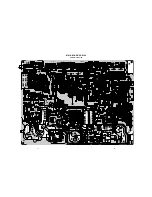
Page 27: ... D101 R106 C106 RS11 RV18 RV17 DV01 QS04 QS02 RS01 CS01 RS15 RS16 RS17 RS18 QV10 RV11 RV12 RV13 RV09 CV10 CV09 RS10 RS09 RS08 RS07 RS06 CS03 QS05 RS19 RS20 RS21 RS26 CS09 CS13 CS12 QS06 RS22 RS23 RS24 RS25 CS10 CS11 CS14 RS04 RS12 RS13 RS14 CS07 CS06 CS05 CS04 CV01 GJ03 GJ04 R158 L150 R136 C605 C898 L814 L811 C817 G810 R820 R829 C823 D810 C822 D815 D806 G812 D817 D819 C821 R826 R814 R823 R804 R807...

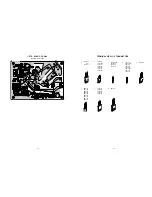
Page 28: ...SD2253 2SD1556 2SC5143 2SD2553 E C B B C E BCE B CE E C B E C B B C E B C E ON4409 29 30 CRT D BOARD PD0393 BOTTOM FOIL SIDE PLC2147 R902 R 9 6 1 R963 R901 R960 R929 R937 C902 Q901 Q905 P502 R928 Q907 R974 C971 C913 R920 C904 G941 C905 G942 C907 G943 G903 G902 R903 C912 C910 R938 D904 D901 D906 Q908 R904 R905 C931 P501 G904 G905 G906 R931 D905 Q903 R921 R922 R925 R936 R915 R914 R917 R977 R972 E B ...

Page 29: ... are 1 6W and 5 tolerance carbon resistor unless otherwise noted as the following marks 1 2R Metal or Metal oxide of 1 2 watt 1 2S Carbon compsistion of 1 2 watt 1RF Fuse resistor of 1 watt 10W Cement of 10 watt K 10 G 2 F 1 2 CAPACITOR Unless otherwise noted in schematic all capacitor values less than 1 are expressed in F and the values more than 1 in pF All capacitors are ceramic 50V unless othe...

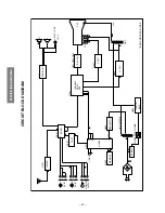
Page 30: ...840 AV IN 1 AV IN 2 MEMORY QT01 TEXT REGULATOR RESET µ COM I 2 C BUS R G B HYBRID CONVERTER TRANS B VOLTAGE C Y CHROMA VIDEO DEF VIDEO OUT V OUT H OUT ERROR AMP F B T H V D Y V H CRT AV SW BUS CONTROL BLOCK V L R R MONITOR OUTPUT V L R V L Q610 AUDIO OUT L R HEADPHONE JACK CIRCUIT BLOCK DIAGRAM ...

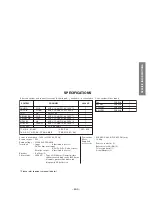
Page 31: ...l picture tube measured diagonally 480 0mm Viewable picture tube measured diagonally 90 deflection Dimensions 630 0 W X 465 0 D X 455 5 H mm Mass 18 4kg Supplied accessories Remote controller 1 Batteries size AA R6 2 Telescopic Aerial 1 Aerial Adaptor 1 Color system Video input SYSTEM PAL B G PAL D K PAL I SECAM B G SECAM D K NTSC M NTSC M NTSC 4 43 CHANNEL CCIR VHF 2 12 UHF 21 69 CATV 1 CHINA VHF...

Page 32: ...TOSHIBA CORPORATION ...

Reviews: