– 12 –
GENERAL ADJUSTMENTS
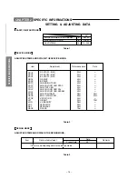
SPECIFIC INFORMATIONS
S1E: Series (Reference factory adjustment)
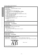
1 AFT/AGC ADJUSTMENT
(Measuring point)
TP-13/TP-14
(Input frequency)
CW: 38.00 [MHz] 95dB
µ
V at 75
Ω
load
(Adjusting method)
1) Open link of IF out.
2) Input 1000pf cap. to link at tuner side to ground.
3) Input frequency after link.
CW: 38.00 [MHz] 95dB
µµµµµ
V at 75
Ω
Ω
Ω
Ω
Ω
load
4) Power On
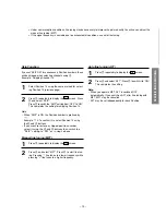
5) Select RFAGC key, on screen display "RAGC OK, Coil OK"
6) If both display OK, adjustment finish; If any one display NG contine as follow
7) Press "0" key display "COIL PRESET"
8) Adjust L161 to 2.5 V
±
0.5V at TP13
9) Press "0" key display "COIL OK"
10) Press RFAGC key on screen display "REAGC ADJUSTING" for 3 secs only
11) DVM display 2.0
±
1.0V at TP14
12) On screen display "RFAGC OK, Coil OK"
13) Power Off.
AFT SPEC : 2.5
±
0.5V (TP13)
AGC SPEC: 2.0
±
1.0V (TP14)
2 SUB COLOUR CONTRAST (SCNT)
(Measuring point)
(Adjusting signal)
NO ADJUSTMENT
(Adjusting method)
3 SUB BRIGHT (BRTC)
(Adjusting signal)
Sub Bright (PAL or NTSC) signal.
(Adjusting method)
1) Set user control to the standard 1.
2) Change BRTC data to set black collapse numbers by eye check.
SPEC 4
±
1.5 bars
*Note: This item to adjust last
4 SUB COLOUR CENTER (COLP)
(Measuring point)
(Adjusting signal)
NO ADJUSTMENT
(Adjusting method)
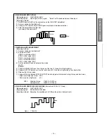
5 SUB TINT CENTER (FOR M-NTSC MODEL) (TNTC)
(Measuring point)
Q501 #22 (B-OUT)
(Adjusting signal)
Sub Bright (NTSC) signal
*Note: For Thailand model use Video input
(Adjusting method)
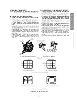
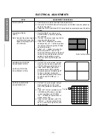
Change TNTC data to adjust the 5th pointion to the 6th level of B-Y signal and the 7th level differ-
ence should regulate to 2:1
SPEC: –5.0
°±
5
°
*Note: This ITEM Adjust before (COLC)
–5
°
1
2
#5
#6
#7


