– 15 –
3.
Removing the Main (Analog) and Main (Digital) boards
3-1. 14JL7E/H/R
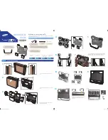
1) Remove the back cover, stand and back cabinet. (Refer to items 1 and 2.)
2) Remove the Inverter unit. (Refer to item 4.)
3) Remove 4 screws, then remove the I/O cover L and I/O cover R.
4) Remove 6 screws, then remove the I/O bracket L.
5) Remove 5 screws, then remove the I/O bracket R.
6) Disconnects 2 wire harnesses and 3 FFC [A].
7) Remove 6 screws, then remove the A/D shield cover.
8) Remove 4 screws, and disconnect 1 FFC [B] and 1 cable on the Main (Digital) board, then remove the Main
(Digital) board.
9) Remove 2 screws, then remove the Main (Analog) board.
PP 3x8
I/O Cover R
I/O Cover L
I/O Bracket L
Main (Analog)
Board
I/O Bracket R
M 3x4
PP 4x6
BITTS
3x6
PP 3x8
M 3x4
???
M 3x4
BITTS
3x6
M 3x4
A
A
B
B
PP 3x8
BITTS
3x6
Cable
Main (Digital) Board
FFC [A]
FFC [A]
FFC [A]
FFC [B]
Harnesses
A/D Shield cover
Summary of Contents for 14JL7E
Page 3: ... 3 ...
Page 4: ... 4 ...
Page 6: ... 6 ...
Page 28: ... 28 ...
Page 30: ... 30 PACKING DISASSEMBLY P900 P800 K902 A701 A704B A704A A707 Y101A Y101B ...
Page 50: ... 56 MEMO ...
Page 52: ......


