8
EN
ES
DE
GR
FR
PT
IT
PL
CZ
Outdoor Unit
Installation Manual
2
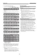
Installation / service tools
Changes in the product and components
In air conditioners using R32, in order to prevent any other refrigerant from being accidentally charged, the service port diameter size of the outdoor unit service
valve has been changed. (1/2 UNF 20 threads per inch)
• In order to increase the pressure resisting strength of the refrigerant piping,
fl
are processing diameter and opposing
fl
are nuts sizes have been changed. (for
copper pipes with nominal dimensions 1/2 and 5/8)
Gauge manifold for R32
Charge hose for R32
Vacuum pump for R32
Gas leakage detector for R32
Phillips screwdriver
Level
Scale
Utility knife
Pipe cutter
Torque wrench
Wrench (or spanner)
Reamer
Flare tool for R32
4 mm hexagonal wrench
3
Speci
fi
cations
RAS-2M10U2AVG-E
RAS-2M14U2AVG-E
RAS-2M18U2AVG-E
RAS-3M18U2AVG-E
Operating conditions
*1
Cooling operation
–10 to 46 °C
Dry operation
–10 to 46 °C
Heating operation
–20 to 24 °C
Connecting pipe length
Minimum for 1 unit
(m)
2
2
2
2
Maximum for 1 unit
(m)
15
20
20
25
Maximum for total unit
(m)
20
30
30
50
Height difference
(m)
10
10
10
10
No additional refrigerant charge (m)
20
30
30
50
The speci
fi
cations for performance of this air conditioner differs depending on the combination of the indoor units which are operated.
*1 If the air conditioner is used in conditions other than the above, the safety protection functions may be activated.
* Example of indoor unit class: RAS-B10UFV-E1 is abbreviated as “10”.
Indoor unit class
Standard connecting pipe diameter
RAS-2M10U2AVG-E
RAS-2M14U2AVG-E
RAS-2M18U2AVG-E
RAS-3M18U2AVG-E
Unit C
07 or 10 or 13
—
—
—
6.35, 9.52 mm
Unit B
07 or 10 or 13 or 16
6.35, 9.52 mm
6.35, 9.52 mm
6.35, 9.52 mm
*3
6.35, 9.52 mm
*3
Unit A
07 or 10 or 13 or 16
6.35, 9.52 mm
6.35, 9.52 mm
6.35, 9.52 mm
*3
6.35, 12.7 mm
*2
Total
20 (RAS-2M10U2AVG-E)
—
26 (RAS-2M14U2AVG-E)
32 (RAS-2M18U2AVG-E)
36 (RAS-3M18U2AVG-E)
All combinations that do not exceed the “Total” number can be installed.
2 or more indoor units must be connected to an outdoor unit.
When 2 indoor units are connected to an outdoor unit, note that some combinations of indoor units are not compatible.
For the further details, refer to the catalogue.
*2 Need the reducer (07, 10, 13 class 12.7 to 9.52 mm).
*3 Need the expander (16 class 9.52 to 12.7 mm).
• Locally procured.
4
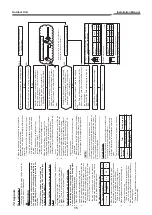
Installation parts, accessories
Installation parts *Locally procured
Parts name
Speci
fi
cations
Q’ty
*4 Refrigerant piping covered with insulating material (Polyethylene
foam, 6 mm thick) When duct-type or cassette-type unit is to
be installed, it shall be covered with thicker insulating material
(Polyethylene foam, 10 mm thick)
Refrigerant piping
*4
Indoor unit
(abbreviation)
Liquid side
(O.D.)
Gas side (O.D.)
1 ea.
07, 10, 13
6.35 mm
9.52 mm
16
6.35 mm
12.7 mm
Putty, PVC tapes
—
1 ea.
Accessories
Installation
manual
1
Rubber cap
(Water-proof)
2
CD-ROM
(Installation
manual)
1
F-GAS label
1
Drain nipple
1
Product
speci
fi
cation
1
Summary of Contents for 13340
Page 17: ......

